API 5CT J55 CASING & TUBING

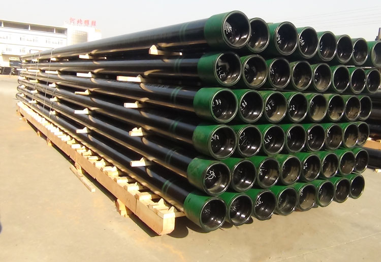
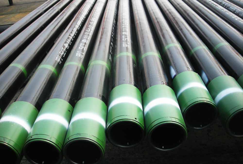
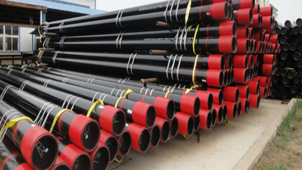
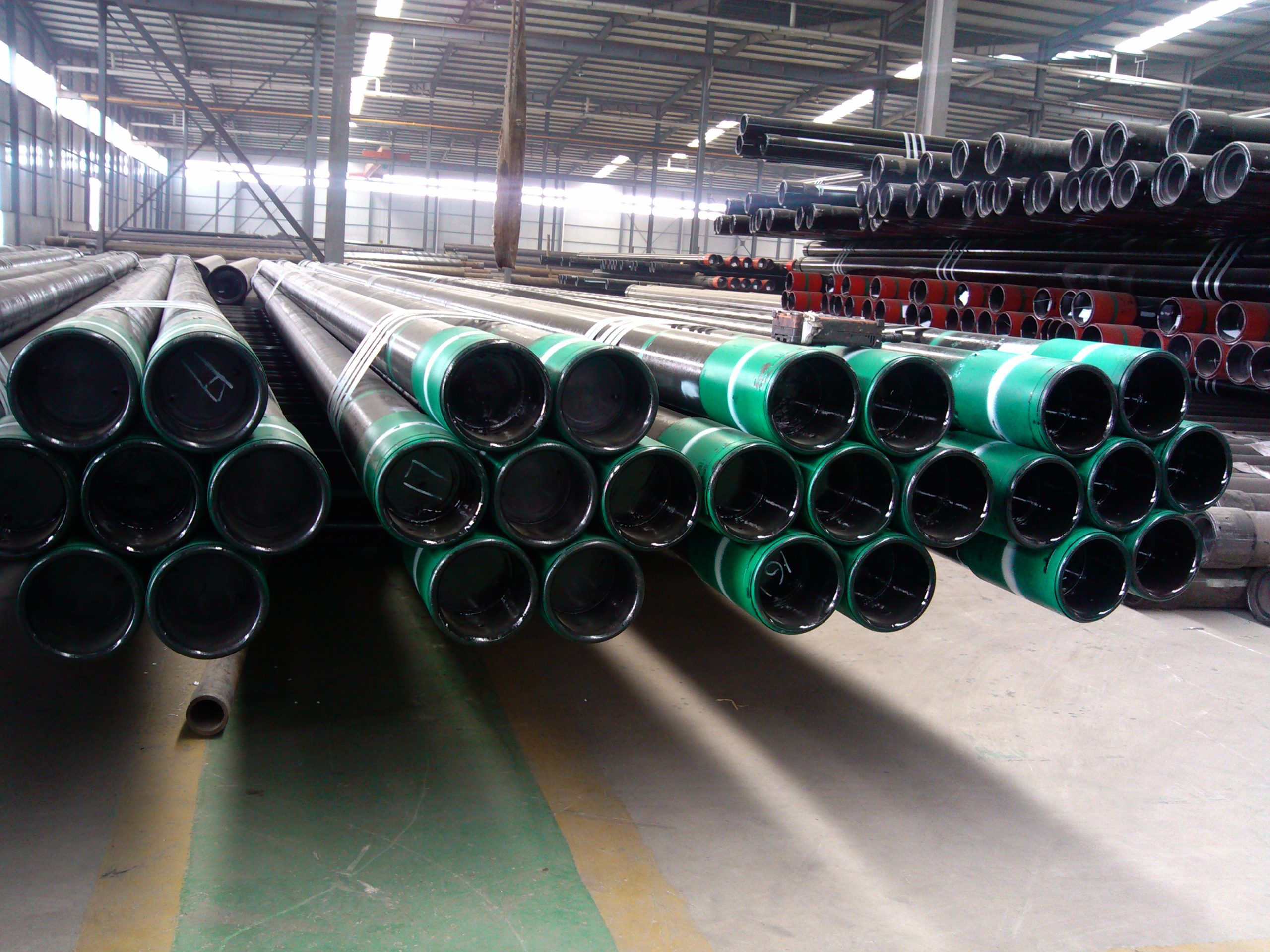
J55 Casing Pipe
Introduction
J55 and K55 casing pipes are widely used in the oil and gas industry for drilling and completing wells. These pipes are part of the API 5CT specification, which outlines the requirements for casing and tubing materials. Both J55 and K55 grades are carbon steel materials offering different mechanical properties suited for various downhole conditions.
API Specifications
Scope
API 5CT specifies the requirements for casing and tubing used in oil and gas wells. It includes details on materials, mechanical properties, dimensions, and testing procedures. J55 and K55 are two grades covered by this specification, each with its own applications and performance characteristics.
Chemical Composition
The chemical composition of J55 and K55 casing steel provides a balance of strength and toughness necessary for wellbore applications. The typical chemical composition for J55 and K55 casing includes:
| Element | Composition (%) |
|---|---|
| Carbon (C) | 0.26 max |
| Manganese (Mn) | 1.10 max |
| Phosphorus (P) | 0.030 max |
| Sulfur (S) | 0.030 max |
| Silicon (Si) | 0.45 max |
Mechanical Properties
The mechanical properties of J55 and K55 casing steel are designed to withstand the pressures and stresses encountered during drilling and production. The typical mechanical properties include:
- J55:
- Tensile Strength: 517-758 MPa (75-110 ksi)
- Yield Strength: Minimum 379 MPa (55 ksi)
- Elongation: Minimum 19% in 2 inches
- K55:
- Tensile Strength: 655-758 MPa (95-110 ksi)
- Yield Strength: Minimum 379 MPa (55 ksi)
- Elongation: Minimum 19% in 2 inches
Pipe Sizes
J55 and K55 casing pipes are available in various sizes to accommodate different wellbore diameters and depths. Standard sizes are specified by their outside diameter (OD) and wall thickness. Common sizes include:
- Outside Diameter (OD): 4 1/2 inches to 20 inches
- Wall Thickness: Varies based on application requirements (e.g., 0.224 inches, 0.250 inches, etc.)
API 5CT J55 CASING & TUBING SPECIFICATIONS
| Code a | Outer Diameter | Nominal Weight | Wall Thickness | End Processing Type | |
|---|---|---|---|---|---|
| (with thread and coupling) b, c | |||||
| mm | kg/m | mm | J55 | ||
| Inch | Lb/ft | K55 | |||
| 1 | 2 | 3 | 4 | 5 | 7 |
| 9 5/8 | 32.3 | 244.48 | 48.07 | 7.92 | – |
| 9 5/8 | 36 | 244.48 | 53.57 | 8.94 | SLB |
| 9 5/8 | 40 | 244.48 | 59.53 | 10.03 | SLB |
| 9 5/8 | 43.5 | 244.48 | 64.73 | 11.05 | – |
| 9 5/8 | 47 | 244.48 | 69.94 | 11.99 | – |
| 9 5/8 | 53.5 | 244.48 | 79.62 | 13.84 | – |
| 9 5/8 | 58.4 | 244.48 | 86.91 | 15.11 | – |
| 10 3/4 | 32.75 | 273.05 | 48.74 | 7.09 | – |
| 10 3/4 | 40.5 | 273.05 | 60.27 | 8.89 | SB |
| 10 3/4 | 45.5 | 273.05 | 67.71 | 10.16 | SB |
| 10 3/4 | 51 | 273.05 | 75.9 | 11.43 | SB |
| 10 3/4 | 55.5 | 273.05 | 82.59 | 12.57 | – |
| 10 3/4 | 60.7 | 273.05 | 90.33 | 13.84 | – |
| 10 3/4 | 65.7 | 273.05 | 97.77 | 15.11 | – |
| 11 3/4 | 42 | 298.45 | 62.5 | 8.46 | – |
| 11 3/4 | 47 | 298.45 | 69.94 | 9.53 | SB |
| 11 3/4 | 54 | 298.45 | 80.36 | 11.05 | SB |
| 11 3/4 | 60 | 298.45 | 89.29 | 12.42 | SB |
| 13 3/8 | 48 | 339.72 | 71.43 | 8.38 | – |
| 13 3/8 | 54.5 | 339.72 | 81.1 | 9.65 | SB |
| 13 3/8 | 61 | 339.72 | 90.78 | 10.92 | SB |
| 13 3/8 | 68 | 339.72 | 101.19 | 12.19 | SB |
| 13 3/8 | 72 | 339.72 | 107.15 | 13.06 | – |
| 16 | 65 | 406.4 | 96.73 | 9.53 | – |
| 16 | 75 | 406.4 | 111.61 | 11.13 | SB |
| 16 | 84 | 406.4 | 125.01 | 12.57 | SB |
| 18 5/8 | 87.5 | 473.08 | 130.21 | 11.05 | SB |
| 20 | 94 | 508 | 139.89 | 11.13 | SLB |
| 20 | 106.5 | 508 | 158.49 | 12.7 | SLB |
| 20 | 133 | 508 | 197.93 | 16.13 | SLB |
| S-Short round thread, L-Long round thread, B-Buttress thread | |||||
| a. Code is used for ordering reference. | |||||
| b. The nominal weight of threaded and coupled casing (column 2) is shown for reference only. | |||||
Dimensions
The dimensions of J55 and K55 casing pipes are specified by their outside diameter (OD) and wall thickness. Standard sizes adhere to API 5CT requirements. Common dimensions include:
- Outside Diameter (OD): 4 1/2 inches to 20 inches
- Wall Thickness: Varies based on application requirements.
Tolerances
API 5CT outlines precise tolerances to ensure the pipes meet quality and performance standards. These tolerances include:
- Outside Diameter (OD): ±1% of the specified OD
- Wall Thickness: ±12.5% of the specified wall thickness
- Weight: ±10% of the nominal weight per unit length
Wall Thickness & Tolerance
The wall thickness of J55 and K55 casing pipes is critical for their performance in drilling and production operations. Tolerances on wall thickness ensure consistent performance. The standard tolerances include:
- Wall Thickness Tolerance: ±12.5% of the specified wall thickness.
- Minimum Wall Thickness: The minimum wall thickness must not be less than 87.5% of the specified nominal wall thickness.
Materials and Manufacture
Materials
J55 and K55 casing pipes are made from carbon steel, which provides a balance of strength, toughness, and cost-effectiveness. The material is suitable for applications where moderate strength and resistance to collapse and internal pressure are required.
Manufacture
The manufacturing process for J55 and K55 casing pipes involves several steps to ensure quality and performance:
- Steelmaking: High-quality carbon steel is produced through processes such as electric arc furnace (EAF) or basic oxygen furnace (BOF).
- Forming: The steel is formed into cylindrical shapes using processes such as seamless rolling or welding.
- Heat Treatment: The pipes may undergo heat treatment processes such as normalizing or quenching and tempering to enhance their mechanical properties.
- Finishing: The pipes are finished to achieve the desired surface quality, dimensions, and tolerances.
Tests
To ensure the quality and performance of J55 and K55 casing pipes, several tests are conducted as per API 5CT requirements:
Hydrostatic Test
A hydrostatic test is performed to verify the pipes’ ability to withstand internal pressure. The pipes are filled with water and pressurized to a specified level to check for leaks and structural integrity.
Nondestructive Testing (NDT)
Nondestructive testing methods are used to detect internal and surface defects without damaging the pipes. Common NDT methods include:
- Ultrasonic Testing: High-frequency sound waves are used to detect internal flaws.
- Magnetic Particle Inspection: Detects surface and near-surface defects using magnetic fields.
Mechanical Tests
Mechanical tests are conducted to verify the pipes’ mechanical properties, including:
- Tensile Test: Measures tensile strength, yield strength, and elongation.
- Hardness Test: Verifies hardness levels to ensure compliance with specified limits.
- Flattening Test: Checks the pipe’s ability to withstand deformation without cracking.
Heat Treatment
Heat treatment processes such as normalizing or quenching and tempering may be applied to J55 and K55 casing pipes to enhance their mechanical properties and ensure consistent performance:
Normalizing
Normalizing involves heating the pipes to a temperature above the critical temperature and then cooling them in air. This process refines the grain structure, improving toughness and strength.
Quenching and Tempering
Quenching and tempering involves heating the pipes to a high temperature, quenching them in water or oil to rapidly cool, and then reheating to a lower temperature to relieve stresses and improve toughness.
J55 and K55 casing steel pipes are essential components in the drilling and production of oil and gas wells. These pipes are manufactured to meet API 5CT standards, ensuring quality, performance, and reliability. Through rigorous manufacturing processes, precise dimensions and tolerances, and comprehensive testing, J55 and K55 casing pipes deliver dependable performance in various drilling and production environments.


