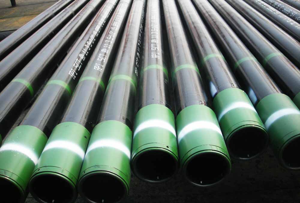
API 5CT Q125 Casing Pipe
API 5CT Q125 Casing Pipe
Introduction
API 5CT is a specification developed by the American Petroleum Institute (API) for casing and tubing materials used in the oil and gas industry. It covers various grades designed to meet different operational and environmental challenges. One of the highest strength grades specified under API 5CT is Q125, which is typically used in ultra-deep wells and other high-pressure environments.
Key Features and Grades
API 5CT Q125 is designed for use in extreme environments where high strength and durability are paramount. Q125 casing and tubing are suitable for operations involving high internal pressures and challenging geological conditions.
Chemical Composition
The chemical composition of API 5CT Q125 ensures high strength and toughness while maintaining good weldability.
- Carbon (C): 0.28 – 0.33%
- Manganese (Mn): 0.90 – 1.20%
- Phosphorus (P): ≤ 0.020%
- Sulfur (S): ≤ 0.010%
- Silicon (Si): 0.15 – 0.35%
- Chromium (Cr): 0.50 – 0.80%
- Molybdenum (Mo): 0.15 – 0.25%
Mechanical Properties
API 5CT Q125 casing and tubing offer exceptional strength and toughness, making them suitable for ultra-deep wells and high-pressure environments.
- Tensile Strength: 862 – 965 MPa (125,000 – 140,000 psi)
- Yield Strength: 862 MPa (125,000 psi) minimum
- Elongation: ≥ 10%
Manufacturing Process
Seamless and Welded Tubing
API 5CT Q125 casing and tubing can be manufactured using either seamless or welded processes, each offering specific advantages depending on the application.
Seamless Process
- Billet Preparation: A solid steel billet is heated and pierced to create a hollow shell.
- Hot Rolling: The hollow shell is rolled to reduce its diameter and wall thickness.
- Cold Drawing (Optional): The tube is cold drawn to achieve precise dimensions and surface finish.
- Heat Treatment: The tube undergoes heat treatment to achieve the required mechanical properties.
- Straightening and Cutting: The tube is straightened and cut to the desired length.
Welded Process
- Strip Preparation: Steel strips are slit to the required width.
- Forming: The strips are formed into a cylindrical shape.
- Welding: The edges of the formed strip are welded together.
- Heat Treatment: The welded tube undergoes heat treatment to achieve the required mechanical properties.
- Sizing and Cutting: The tube is sized and cut to the required length.
Heat Treatment
Heat treatment is crucial to achieve the desired mechanical properties. For Q125 grade, the typical heat treatments include:
- Quenching and Tempering: Heating the tube to a high temperature, then rapidly cooling (quenching) and reheating to a lower temperature (tempering) to achieve the desired strength and toughness.
Testing Requirements
API 5CT specifies rigorous testing requirements to ensure the quality and performance of Q125 casing and tubing:
- Tensile Test: Measures tensile strength, yield strength, and elongation.
- Hardness Test: Ensures the material meets specified hardness levels.
- Impact Test: Assesses the material’s toughness at various temperatures.
- Hydrostatic Test: Ensures the tube can withstand internal pressure without leaking.
- Non-Destructive Testing: Includes ultrasonic, magnetic particle, and radiographic testing to detect any defects.
- Sour Service Testing: Ensures resistance to sulfide stress cracking (SSC) for use in sour environments.
API 5CT Q125 Casing Tubing applicable end-finish
Casing List (sizes, masses, wall thickness, grade, and applicable end-finish)
| Labels | Outside diameter (d/mm) |
T&C (kg/m) |
Wall thickness (t/mm) |
Type of end-finish | |||||||
| 1 | 2 | J55/K55 | M65 | L80/R95 | N80-1/Q | C90/T95 | P110 | Q125 | |||
| 4-1/2 | 9.50 | 114.30 | 14.14 | 5.21 | PS | PS | – | – | – | – | – |
| 10.50 | 114.30 | 15.63 | 5.69 | PSB | PSB | – | – | – | – | – | |
| 11.60 | 114.30 | 17.26 | 6.35 | PSLB | PLB | PLB | PLB | PLB | PLB | – | |
| 13.50 | 114.30 | 20.09 | 7.37 | – | PLB | PLB | PLB | PLB | PLB | – | |
| 15.10 | 114.30 | 22.47 | 8.56 | – | – | – | – | – | PLB | PLB | |
| 5 | 11.50 | 127.00 | 17.11 | 5.59 | PS | PS | – | – | – | – | – |
| 13.00 | 127.00 | 19.35 | 6.43 | PSLB | PSLB | – | – | – | – | – | |
| 15.00 | 127.00 | 22.32 | 7.52 | PSLB | PLB | SLB | PLB | PLB | PLB | ||
| 18.00 | 127.00 | 26.79 | 9.19 | – | PLB | SLB | PLB | PLB | PLB | PLB | |
| 21.40 | 127.00 | 31.85 | 11.10 | – | PLB | PLB | PLB | PLB | PLB | PLB | |
| 23.20 | 127.00 | 34.53 | 12.14 | – | – | PLB | PLB | PLB | PLB | PLB | |
| 24.10 | 127.00 | 35.87 | 12.70 | – | – | PLB | PLB | PLB | PLB | PLB | |
| 5-1/2 | 14.00 | 139.70 | 20.83 | 6.20 | PS | PS | – | – | – | – | – |
| 15.50 | 139.70 | 23.07 | 6.98 | PSLB | PSLB | – | – | – | – | – | |
| 17.00 | 139.70 | 25.30 | 7.72 | PSLB | PLB | PLB | PLB | PLB | PLB | – | |
| 20.00 | 139.70 | 29.76 | 9.17 | – | PLB | PLB | PLB | PLB | PLB | – | |
| 23.00 | 139.70 | 34.23 | 10.54 | – | PLB | PLB | PLB | PLB | PLB | PLB | |
| 26.80 | 139.70 | 39.88 | 12.70 | – | – | – | – | P | – | – | |
| 29.70 | 139.70 | 44.20 | 14.27 | – | – | – | – | P | – | – | |
| 32.60 | 139.70 | 48.52 | 15.88 | – | – | – | – | P | – | – | |
| 35.30 | 139.70 | 52.53 | 17.45 | – | – | – | – | P | – | – | |
| 38.00 | 139.70 | 56.55 | 19.05 | – | – | – | – | P | – | – | |
| 40.50 | 139.70 | 60.27 | 20.62 | – | – | – | – | P | – | – | |
| 43.10 | 139.70 | 64.14 | 22.22 | – | – | – | – | P | – | – | |
| 6-5/8 | 20.00 | 168.28 | 29.76 | 7.32 | PSLB | PSLB | – | – | – | – | – |
| 24.00 | 168.28 | 35.72 | 8.94 | PSLB | PLB | PLB | PLB | PLB | PLB | – | |
| 28.00 | 168.28 | 41.67 | 10.59 | – | PLB | PLB | PLB | PLB | PLB | – | |
| 32.00 | 168.28 | 47.62 | 12.06 | – | – | PLB | PLB | PLB | PLB | PLB | |
| 7 | 17.00 | 177.80 | 25.30 | 5.87 | – | – | – | – | – | – | – |
| 20.00 | 177.80 | 29.76 | 6.91 | PS | PS | – | – | – | – | – | |
| 23.00 | 177.80 | 34.23 | 8.05 | PSLB | PLB | PLB | PLB | PLB | – | – | |
| 26.00 | 177.80 | 38.69 | 9.19 | – | PLB | PLB | PLB | PLB | PLB | – | |
| 29.00 | 177.80 | 43.16 | 10.36 | – | PLB | PLB | PLB | PLB | PLB | – | |
| 32.00 | 177.80 | 47.62 | 11.51 | – | PLB | PLB | PLB | PLB | PLB | – | |
| 35.00 | 177.80 | 52.09 | 12.65 | – | – | PLB | PLB | PLB | PLB | PLB | |
| 38.00 | 177.80 | 56.55 | 13.72 | – | – | PLB | PLB | PLB | PLB | PLB | |
| 42.70 | 177.80 | 63.55 | 15.88 | – | – | – | – | P | – | – | |
| 46.40 | 177.80 | 69.05 | 17.45 | – | – | – | – | P | – | – | |
| 50.10 | 177.80 | 74.56 | 19.05 | – | – | – | – | P | – | – | |
| 53.60 | 177.80 | 79.77 | 20.62 | – | – | – | – | P | – | – | |
| 57.10 | 177.80 | 84.98 | 22.22 | – | – | – | – | P | – | – | |
| 7-5/8 | 24.00 | 193.68 | 35.72 | 7.62 | – | – | – | – | – | – | |
| 26.40 | 193.68 | 39.29 | 8.33 | PSLB | PSLB | PLB | PLB | PLB | – | – | |
| 29.70 | 193.68 | 44.20 | 9.52 | – | PLB | PLB | PLB | PLB | PLB | – | |
| 33.70 | 193.68 | 50.15 | 10.92 | – | PLB | PLB | PLB | PLB | PLB | – | |
| 39.00 | 193.68 | 58.04 | 12.70 | – | – | PLB | PLB | PLB | PLB | PLB | |
| 42.80 | 193.68 | 63.69 | 14.27 | – | – | PLB | PLB | PLB | PLB | PLB | |
| 45.30 | 193.68 | 67.42 | 15.11 | – | – | PLB | PLB | PLB | PLB | PLB | |
| 47.10 | 193.68 | 70.09 | 15.88 | – | – | PLB | PLB | PLB | PLB | PLB | |
| 51.20 | 193.68 | 76.20 | 17.45 | – | – | – | – | P | – | – | |
| 55.30 | 193.68 | 82.30 | 19.05 | – | – | – | – | P | – | – | |
| 7-3/4 | 46.10 | 196.85 | 68.61 | 15.11 | – | – | P | P | P | P | P |
| 8-5/8 | 24.00 | 219.08 | 35.72 | 6.71 | PS | PS | – | – | – | – | – |
| 28.00 | 219.08 | 41.67 | 7.72 | PS | – | – | – | – | – | ||
| 32.00 | 219.08 | 47.62 | 8.94 | PSLB | PSLB | – | – | – | – | – | |
| 36.00 | 219.08 | 53.58 | 10.16 | PSLB | PSLB | PLB | PLB | PLB | PLB | – | |
| 40.00 | 219.08 | 59.53 | 11.43 | – | PLB | PLB | PLB | PLB | PLB | – | |
| 44.00 | 219.08 | 65.48 | 12.70 | – | – | PLB | PLB | PLB | PLB | – | |
| 49.00 | 219.08 | 72.92 | 14.15 | – | – | PLB | PLB | PLB | PLB | PLB | |
| 9-5/8 | 32.30 | 244.48 | 48.07 | 7.92 | – | – | – | – | – | – | – |
| 36.00 | 244.48 | 53.58 | 8.94 | PSLB | PSLB | – | – | – | – | – | |
| 40.00 | 244.48 | 59.53 | 10.03 | PSLB | PSLB | PLB | PLB | PLB | – | – | |
| 43.50 | 244.48 | 64.74 | 11.05 | – | PLB | PLB | PLB | PLB | PLB | – | |
| 47.00 | 244.48 | 69.95 | 11.99 | – | PLB | PLB | PLB | PLB | PLB | PLB | |
| 53.50 | 244.48 | 79.62 | 13.84 | – | – | PLB | PLB | PLB | PLB | PLB | |
| 58.40 | 244.48 | 86.91 | 15.11 | – | – | PLB | PLB | PLB | PLB | PLB | |
| 59.40 | 244.48 | 88.40 | 15.47 | – | – | – | – | P | – | – | |
| 64.90 | 244.48 | 96.58 | 17.07 | – | – | – | – | P | – | – | |
| 70.30 | 244.48 | 104.62 | 18.64 | – | – | – | – | P | – | – | |
| 75.60 | 244.48 | 112.51 | 20.24 | – | – | – | – | P | – | – | |
| 10-3/4 | 32.75 | 273.05 | 48.74 | 7.09 | – | – | – | – | – | – | – |
| 40.50 | 273.05 | 60.27 | 8.89 | PSB | PSB | – | – | – | – | – | |
| 45.50 | 273.05 | 67.71 | 10.16 | PSB | PSB | – | – | – | – | – | |
| 51.00 | 273.05 | 75.90 | 11.43 | PSB | PSB | PSB | PSB | PSB | PSB | – | |
| 55.50 | 273.05 | 82.60 | 12.57 | – | PSB | PSB | PSB | PSB | PSB | – | |
| 60.70 | 273.05 | 90.33 | 13.84 | – | – | – | – | PSB | PSB | PSB | |
| 65.70 | 273.05 | 97.77 | 15.11 | – | – | – | – | PSB | PSB | PSB | |
| 73.20 | 273.05 | 108.94 | 17.07 | – | – | – | – | P | – | – | |
| 79.20 | 273.05 | 117.87 | 18.64 | – | – | – | – | P | – | – | |
| 85.30 | 273.05 | 126.94 | 20.24 | – | – | – | – | P | – | – | |
| 11-3/4 | 42.00 | 298.45 | 62.50 | 8.46 | – | – | – | – | – | – | – |
| 47.00 | 298.45 | 69.95 | 9.53 | PSB | PSB | – | – | – | – | – | |
| 54.00 | 298.45 | 80.36 | 11.05 | PSB | PSB | – | – | – | – | – | |
| 60.00 | 298.45 | 89.29 | 12.42 | PSB | PSB | PSB | PSB | PSB | PSB | PSB | |
| 65.00 | 298.45 | 96.73 | 13.56 | – | – | P | P | P | P | P | |
| 71.00 | 298.45 | 105.66 | 14.78 | – | – | P | P | P | P | P | |
| 13-3/8 | 48.00 | 339.72 | 71.43 | 8.38 | – | – | – | – | – | – | – |
| 54.50 | 339.72 | 81.11 | 9.65 | PSB | PSB | – | – | – | – | – | |
| 61.00 | 339.72 | 90.78 | 10.92 | PSB | PSB | – | – | – | – | – | |
| 68.00 | 339.72 | 101.20 | 12.19 | PSB | PSB | PSB | PSB | PSB | PSB | – | |
| 72.00 | 339.72 | 107.15 | 13.06 | – | – | PSB | PSB | PSB | PSB | PSB | |
| 16 | 65.00 | 406.40 | 96.73 | 9.53 | – | – | – | – | – | – | – |
| 75.00 | 406.40 | 111.62 | 11.13 | PSB | PSB | – | – | – | – | – | |
| 84.00 | 406.40 | 125.01 | 12.57 | PSB | PSB | – | – | – | – | – | |
| 109.00 | 406.40 | 162.21 | 16.66 | P | – | P | P | – | P | P | |
| 18-5/8 | 87.50 | 473.08 | 130.22 | 11.05 | PSB | PSB | – | – | – | – | – |
| 20 | 94.00 | 508.00 | 139.89 | 11.13 | PSLB | PSLB | – | – | – | – | – |
| 106.50 | 508.00 | 158.49 | 12.70 | PSLB | PSLB | – | – | – | – | – | |
| 133.00 | 508.00 | 197.93 | 16.13 | PSLB | – | – | – | – | – | – | |
* P – plain end, S – short round thread, B – buttress, L – long round thread.
| API 5CT Q125 Casing Tubing Grade Color Codes | ||||
| Grade | Grade Type | Number and Color of Bands for Product a with Length ³ 1.8 m | Color(s) for Couplings | |
| Entire Coupling | Band(s) b, c | |||
| 1 | 2 | 3 | 4 | 5 |
| H40 | — | None or black band at the manufacturer’s option | None | Same as for pipe |
| J55 Tubing | — | One bright green | Bright green | None |
| J55 Casing | — | One bright green | Bright green | One white |
| K55 | — | Two bright green | Bright green | None |
| N80 | 1 | One red | Red | None |
| N80 | Q | One red, one bright green | Red | Green |
| R95 | — | One brown | Brown | None |
| L80 | 1 | One red, one brown | Red | One brown |
| L80 | 9Cr | One red, one brown, two yellow | None | Two yellow |
| L80 | 13Cr | One red, one brown, one yellow | None | One yellow |
| C90 | 1 | One purple | Purple | None |
| T95 | 1 | One silver | Silver | None |
| C110 | — | One white, two brown | White | Two brown |
| P110 | — | One white | White | None |
| Q125 | 1 | One orange | Orange | None |
| a In the case of coupling material, unless otherwise specified in the purchase agreement, the manufacturer’s internal requirements shall govern. | ||||
| b Special clearance couplings shall also have a black band. | ||||
| c Seal-ring couplings shall also have a blue band. | ||||
| API 5CT Q125 Casing Tubing
Dimensions and Masses for Standard Casing and for Casing Threaded with |
|||||||||||
| API Round Thread and Buttress Thread | |||||||||||
| Labels a | Calculated Mass c | ||||||||||
| Nominal Linear Mass T& C b,c | Wall Thick- ness | em, Mass Gain or Loss Due to End Finishing d | |||||||||
| Outside Diameter | Inside Diameter | Drift Diameter | Plain- end | kg | |||||||
| Round Thread | Buttress Thread | ||||||||||
| wpe | |||||||||||
| D | kg/m | t | D | mm | kg/m | Short | Long | RC | SCC | ||
| mm | mm | mm | |||||||||
| 1 | 2 | 3 | 4 | 5 | 6 | 7 | 8 | 9 | 10 | 11 | 12 |
| 4 1/2 | 9.5 | 114.3 | 14.38 | 5.21 | 103.88 | 100.7 | 14.02 | 3.64 | — | — 4.53 | — 1.12 |
| 4 1/2 | 10.5 | 114.3 | 15.73 | 5.69 | 102.92 | 99.74 | 15.24 | 3.33 | — 3.61 | 4.32 | 0.91 |
| 4 1/2 | 11.6 | 114.3 | 17.38 | 6.35 | 101.6 | 98.42 | 16.91 | 3.18 | 3.35 | 4.07 | 0.6 |
| 4 1/2 | 13.5 | 114.3 | 19.87 | 7.37 | 99.56 | 96.38 | 19.44 | — | 3.53 | 3.64 | 0.24 |
| 4 1/2 | 15.1 | 114.3 | 22.69 | 8.56 | 97.18 | 94 | 22.32 | — | |||
| 5 | 11.5 | 127 | 17.19 | 5.59 | 115.82 | 112.64 | 16.74 | 4.32 | — 4.85 | — 5.38 | — 1.24 |
| 5 | 13 | 127 | 19.69 | 6.43 | 114.14 | 110.96 | 19.12 | 4 | 4.51 | 4.99 | 0.61 |
| 5 | 15 | 127 | 22.69 | 7.52 | 111.96 | 108.78 | 22.16 | 3.71 | 4.52 | 4.4 | 0.22 |
| 5 | 18 | 127 | 27.19 | 9.19 | 108.62 | 105.44 | 26.7 | — | 3.45 | 3.76 | –0.62 |
| 5 | 21.4 | 127 | 32.13 | 11.1 | 104.8 | 101.62 | 31.73 | — | 3.15 | 3.42 | –0.96 |
| 5 | 23.2 | 127 | 34.76 | 12.14 | 102.72 | 99.54 | 34.39 | — | 2.99 | 3.23 | –1.14 |
| 5 | 24.1 | 127 | 36.15 | 12.7 | 101.6 | 98.42 | 35.8 | — | |||
| 5 1/2 | 14 | 139.7 | 20.91 | 6.2 | 127.3 | 124.12 | 20.41 | 4.6 | — 5.26 | — 5.71 | — 0.87 |
| 5 1/2 | 15.5 | 139.7 | 23.48 | 6.98 | 125.74 | 122.56 | 22.85 | 4.36 | 5.31 | 5.41 | 0.58 |
| 5 1/2 | 17 | 139.7 | 25.72 | 7.72 | 124.26 | 121.08 | 25.13 | 4.14 | 4.5 | 4.84 | 0.45 |
| 5 1/2 | 20 | 139.7 | 30.05 | 9.17 | 121.36 | 118.18 | 29.52 | — | 4.37 | 4.31 | -0.52 |
| 5 1/2 | 23 | 139.7 | 34.05 | 10.54 | 118.62 | 115.44 | 33.57 | — | — | — | — |
| 5 1/2 | 26.8 | 139.7 | 40.15 | 12.7 | 114.3 | 111.12 | 39.78 | — | — | — | — |
| 5 1/2 | 29.7 | 139.7 | 44.47 | 14.27 | 111.16 | 107.98 | 44.14 | — | — | — | — |
| 5 1/2 | 32.6 | 139.7 | 48.74 | 15.88 | 107.94 | 104.76 | 48.49 | — | — | — | — |
| 5 1/2 | 35.3 | 139.7 | 52.8 | 17.45 | 104.8 | 101.62 | 52.61 | — | — | — | — |
| 5 1/2 | 38 | 139.7 | 56.82 | 19.05 | 101.6 | 98.42 | 56.68 | — | — | — | — |
| 5 1/2 | 40.5 | 139.7 | 60.64 | 20.62 | 98.46 | 95.28 | 60.55 | — | — | — | — |
| 5 1/2 | 43.1 | 139.7 | 64.41 | 22.22 | 95.26 | 92.08 | 64.38 | — | |||
| 6 5/8 | 20 | 168.28 | 29.76 | 7.32 | 153.64 | 150.46 | 29.06 | 5.58 | 6.23 | 6.35 | 0.89 |
| 6 5/8 | 24 | 168.28 | 35.72 | 8.94 | 150.4 | 147.22 | 35.13 | 4.42 | 5.48 | 5.52 | 0.68 |
| 6 5/8 | 28 | 168.28 | 41.67 | 10.59 | 147.1 | 143.92 | 41.18 | — | 4.73 | 4.71 | –0.75 |
| 6 5/8 | 32 | 168.28 | 47.62 | 12.06 | 144.16 | 140.98 | 46.46 | — | 4.73 | 4 | –1.46 |
| Calculated Mass c | |||||||||||
| Nominal Linear Mass T& C b,c | Wall Thick- ness | em, Mass Gain or Loss Due to End Finishing d | |||||||||
| Labels a | Outside Diameter | Inside Diameter | Drift Diameter | Plain- end | kg | ||||||
| Round Thread | Buttress Thread | ||||||||||
| wpe | |||||||||||
| D | kg/m | t | D | mm | kg/m | Short | Long | RC | SCC | ||
| mm | mm | mm | |||||||||
| 1 | 2 | 3 | 4 | 5 | 6 | 7 | 8 | 9 | 10 | 11 | 12 |
| 7 | 17 | 177.8 | 25.6 | 5.87 | 166.06 | 162.88 | 24.89 | 7.61 | — | — | — |
| 7 | 20 | 177.8 | 29.91 | 6.91 | 163.98 | 160.8 | 29.12 | 6.74 | — 7.94 | — 8.28 | — 0.58 |
| 7 | 23 | 177.8 | 34.67 | 8.05 | 161.7 | 158.75 e 158.52 156.24 153.90 | 33.7 | 6.26 | 7.94 | 8.28 | 0.58 |
| 7 | 23 | 177.8 | 34.67 | 8.05 | 161.7 | 152.40 e | 33.7 | 6.26 | 7.37 | 7.65 | –0.54 |
| 7 | 26 | 177.8 | 39.14 | 9.19 | 159.42 | 151.6 | 38.21 | 5.79 | 6.79 | 7.13 | –0.69 |
| 7 | 29 | 177.8 | 43.6 | 10.36 | 157.08 | 149.32 | 42.78 | — | 6.23 | 6.4 | –1.31 |
| 7 | 32 | 177.8 | 47.92 | 11.51 | 154.78 | 147.18 | 47.2 | — | 6.23 | 6.4 | –1.31 |
| 7 | 32 | 177.8 | 47.92 | 11.51 | 154.78 | 142.86 | 47.2 | — | 5.68 | 5.79 | –1.91 |
| 7 | 35 | 177.8 | 52.09 | 12.65 | 152.5 | 139.72 | 51.52 | — | 5.18 | 5.24 | –2.47 |
| 7 | 38 | 177.8 | 56.1 | 13.72 | 150.36 | 136.52 | 55.52 | — | — | — | — |
| 7 | 42.7 | 177.8 | 63.84 | 15.88 | 146.04 | 133.38 | 63.41 | — | — | — | — |
| 7 | 46.4 | 177.8 | 69.35 | 17.45 | 142.9 | 130.18 | 69.01 | — | — | — | — |
| 7 | 50.1 | 177.8 | 74.85 | 19.05 | 139.7 | 74.58 | — | — | — | — | |
| 7 | 53.6 | 177.8 | 80.21 | 20.62 | 136.56 | 79.93 | — | — | — | — | |
| 7 | 57.1 | 177.8 | 85.42 | 22.22 | 133.36 | 85.25 | — | ||||
| 7 5/8 | 24 | 193.68 | 35.72 | 7.62 | 178.44 | 175.26 | 34.96 | 7.11 | — 8.58 | — 9.12 | — 2.59 |
| 7 5/8 | 26.4 | 193.68 | 39.29 | 8.33 | 177.02 | 173.84 | 38.08 | 6.78 | 7.91 | 8.38 | 1.84 |
| 7 5/8 | 29.7 | 193.68 | 44.2 | 9.52 | 174.64 | 171.46 | 43.24 | — | 7.13 | 7.51 | 0.98 |
| 7 5/8 | 33.7 | 193.68 | 50.15 | 10.92 | 171.84 | 168.66 | 49.22 | — | 6.16 | 6.44 | – 0.10 |
| 7 5/8 | 39 | 193.68 | 58.04 | 12.7 | 168.28 | 165.1 | 56.68 | — | 5.32 | 5.5 | –1.03 |
| 7 5/8 | 42.8 | 193.68 | 63.69 | 14.27 | 165.14 | 161.96 | 63.14 | — | 4.87 | 5.01 | –1.52 |
| 7 5/8 | 45.3 | 193.68 | 67.41 | 15.11 | 163.46 | 160.28 | 66.54 | — | 4.48 | 4.57 | –1.96 |
| 7 5/8 | 47.1 | 193.68 | 70.09 | 15.88 | 161.92 | 158.74 | 69.63 | — | — | — | — |
| 7 5/8 | 51.2 | 193.68 | 76.19 | 17.45 | 158.78 | 155.6 | 75.84 | — | — | — | — |
| 7 5/8 | 55.3 | 193.68 | 82.3 | 19.05 | 155.58 | 152.4 | 82.04 | — | |||
| 7 3/4 | 46.1 | 196.85 | 68.6 | 15.11 | 166.63 | 165.10 e | 67.72 | — | — | — | — |
| 7 3/4 | 46.1 | 196.85 | 68.6 | 15.11 | 166.63 | 163.45 | 67.72 | — | — | — | — |
| Labels a | Calculated Mass c | ||||||||||
| Nominal Linear Mass T& C b,c | Wall Thick- ness | em, Mass Gain or Loss Due to End Finishing d | |||||||||
| Outside Diameter | Inside Diameter | Drift Diameter | Plain- end | kg | |||||||
| Round Thread | Buttress Thread | ||||||||||
| wpe | |||||||||||
| D | kg/m | t | D | mm | kg/m | Short | Long | RC | SCC | ||
| mm | mm | mm | |||||||||
| 1 | 2 | 3 | 4 | 5 | 6 | 7 | 8 | 9 | 10 | 11 | 12 |
| 8 5/8 | 24 | 219.08 | 35.72 | 6.71 | 205.66 | 202.48 | 35.14 | 10.93 | — | — | — |
| 8 5/8 | 28 | 219.08 | 41.67 | 7.72 | 203.64 | 200.46 | 40.24 | 10.07 | — 12.44 | — 12.57 | — 2.51 |
| 8 5/8 | 32 | 219.08 | 47.62 | 8.94 | 201.2 | 200.02 e 198.02 195.58 | 46.33 | 9.39 | 12.44 | 12.57 | 2.51 |
| 8 5/8 | 32 | 219.08 | 47.62 | 8.94 | 201.2 | 193.68 e | 46.33 | 9.39 | 11.6 | 11.68 | 1.62 |
| 8 5/8 | 36 | 219.08 | 53.57 | 10.16 | 198.76 | 193.04 | 52.35 | 8.72 | 10.73 | 10.77 | 0.71 |
| 8 5/8 | 40 | 219.08 | 59.53 | 11.43 | 196.22 | 190.5 | 58.53 | — | 10.73 | 10.77 | 0.71 |
| 8 5/8 | 40 | 219.08 | 59.53 | 11.43 | 196.22 | 187.6 | 58.53 | — | 9.88 | 9.87 | –0.20 |
| 8 5/8 | 44 | 219.08 | 65.48 | 12.7 | 193.68 | 64.64 | — | 8.88 | 8.85 | –1.21 | |
| 8 5/8 | 49 | 219.08 | 72.92 | 14.15 | 190.78 | 71.51 | — | ||||
| 9 5/8 | 32.3 | 244.48 | 48.07 | 7.92 | 228.6 | 224.66 | 46.2 | 11 | — 14.48 | — 13.87 | — 2.74 |
| 9 5/8 | 36 | 244.48 | 53.57 | 8.94 | 226.6 | 222.63 | 51.93 | 10.36 | 13.59 | 12.97 | 1.84 |
| 9 5/8 | 40 | 244.48 | 59.53 | 10.03 | 224.4 | 222.25 e 220.45 218.41 218.41 216.54 216.54 | 57.99 | 9.69 | 13.59 | 12.97 | 1.84 |
| 9 5/8 | 40 | 244.48 | 59.53 | 10.03 | 224.4 | 215.90 e | 57.99 | 9.69 | 12.78 | 12.15 | 1.01 |
| 9 5/8 | 43.5 | 244.48 | 64.74 | 11.05 | 222.4 | 215.90 e 212.83 212.83 | 63.61 | — | 12.84 f | 12.15 | 1.01 |
| 9 5/8 | 43.5 | 244.48 | 64.74 | 11.05 | 222.4 | 212.72 e | 63.61 | — | 12.03 | 11.39 | 0.25 |
| 9 5/8 | 47 | 244.48 | 69.94 | 11.99 | 220.5 | 212.72 e 210.29 210.29 209.58 206.38 203.23 200.02 | 68.75 | — | 12.09 f | 11.39 | 0.25 |
| 9 5/8 | 47 | 244.48 | 69.94 | 11.99 | 222.5 | 68.75 | — | 10.57 | 9.92 | –1.22 | |
| 9 5/8 | 53.5 | 244.48 | 79.62 | 13.84 | 216.8 | 78.72 | — | 10.63 f | 9.92 | –1.22 | |
| 9 5/8 | 53.5 | 244.48 | 79.62 | 13.84 | 216.8 | 78.72 | — | 10.57 | 9.92 | –1.22 | |
| 9 5/8 | 53.5 | 244.48 | 79.62 | 13.84 | 216.8 | 78.72 | — | 10.63 f | 9.92 | –1.22 | |
| 9 5/8 | 53.5 | 244.48 | 79.62 | 13.84 | 216.8 | 78.72 | — | 9.58 | 8.92 | –2.22 | |
| 9 5/8 | 58.4 | 244.48 | 86.91 | 15.11 | 214.25 | 85.47 | — | 9.65 f | 8.92 | –2.22 | |
| 9 5/8 | 58.4 | 244.48 | 86.91 | 15.11 | 214.25 | 85.47 | — | 9.58 | 8.92 | –2.22 | |
| 9 5/8 | 58.4 | 244.48 | 86.91 | 15.11 | 214.25 | 85.47 | — | 9.65 f | 8.92 | –2.22 | |
| 9 5/8 | 58.4 | 244.48 | 86.91 | 15.11 | 214.25 | 85.47 | — | — | — | — | |
| 9 5/8 | 59.4 | 244.48 | 88.4 | 15.47 | 213.5 | 87.37 | — | — | — | — | |
| 9 5/8 | 64.9 | 244.48 | 96.58 | 17.07 | 210.3 | 95.73 | — | — | — | — | |
| 9 5/8 | 70.3 | 244.48 | 104.62 | 18.64 | 207.2 | 103.82 | — | — | — | — | |
| 9 5/8 | 75.6 | 244.48 | 112.51 | 20.24 | 204 | 111.93 | — | ||||
| Calculated Mass c | |||||||||||
| Nominal Linear Mass T& C b,c | Wall Thick- ness | em, Mass Gain or Loss Due to End Finishing d | |||||||||
| Labels a | Outside Diameter | Inside Diameter | Drift Diameter | Plain- end | kg | ||||||
| Round Thread | Buttress Thread | ||||||||||
| wpe | |||||||||||
| D | kg/m | t | D | mm | kg/m | Short | Long | RC | SCC | ||
| mm | mm | mm | |||||||||
| 1 | 2 | 3 | 4 | 5 | 6 | 7 | 8 | 9 | 10 | 11 | 12 |
| 10 3/4 | 32.75 | 273.05 | 48.74 | 7.09 | 258.9 | 254.91 | 46.5 | 13.94 | — | — 15.38 | — 3.03 |
| 10 3/4 | 40.5 | 273.05 | 60.27 | 8.89 | 255.3 | 251.31 | 57.91 | 11.91 | — | 14.21 | 1.86 |
| 10 3/4 | 45.5 | 273.05 | 67.71 | 10.16 | 252.7 | 250.82 e 248.77 246.23 246.33 | 65.87 | 11 | — | 14.21 | 1.86 |
| 10 3/4 | 45.5 | 273.05 | 67.71 | 10.16 | 252.7 | 244.48 e | 65.87 | 11 | — | 13.05 | 0.7 |
| 10 3/4 | 51 | 273.05 | 75.9 | 11.43 | 250.2 | 244.48 e 243.94 243.94 241.40 241.40 238.86 238.86 234.95 231.80 228.60 | 73.75 | 10.11 | — | 13.05 | 0.7 |
| 10 3/4 | 51 | 273.05 | 75.9 | 11.43 | 250.2 | 73.75 | 10.16 f | — | 12.25 | –0.09 | |
| 10 3/4 | 55.5 | 273.05 | 82.59 | 12.57 | 247.9 | 80.75 | 9.3 | — | 12.01 | –0.34 | |
| 10 3/4 | 55.5 | 273.05 | 82.59 | 12.57 | 247.9 | 80.75 | 9.35 f | — | 12.25 | –0.09 | |
| 10 3/4 | 55.5 | 273.05 | 82.59 | 12.57 | 247.9 | 80.75 | 9.3 | — | 12.01 | –0.34 | |
| 10 3/4 | 55.5 | 273.05 | 82.59 | 12.57 | 247.9 | 80.75 | 9.35 f | — | 11.07 | — | |
| 10 3/4 | 60.7 | 273.05 | 90.33 | 13.84 | 245.4 | 88.47 | 8.42 | — | 10.87 | — | |
| 10 3/4 | 60.7 | 273.05 | 90.33 | 13.84 | 245.4 | 88.47 | 8.47 f | — | 9.98 | — | |
| 10 3/4 | 65.7 | 273.05 | 97.77 | 15.11 | 242.8 | 96.12 | 7.54 | — | 9.74 | — | |
| 10 3/4 | 65.7 | 273.05 | 97.77 | 15.11 | 242.8 | 96.12 | 7.60 f | — | — | — | |
| 10 3/4 | 73.2 | 273.05 | 108.93 | 17.07 | 238.9 | 107.76 | — | — | — | — | |
| 10 3/4 | 79.2 | 273.05 | 117.86 | 18.64 | 235.8 | 116.95 | — | — | — | — | |
| 10 3/4 | 85.3 | 273.05 | 126.94 | 20.24 | 232.6 | 126.19 | — | — | |||
| 11 3/4 | 42 | 298.45 | 62.5 | 8.46 | 281.5 | 279.40 e 277.50 275.44 272.39 | 62.56 | 13.27 | — | — | — |
| 11 3/4 | 42 | 298.45 | 62.5 | 8.46 | 281.5 | 269.88 e | 62.56 | 13.27 | — | — 16.04 | — |
| 11 3/4 | 47 | 298.45 | 69.94 | 9.52 | 279.41 | 269.88 e | 67.83 | 12.42 | — | 14.5 | — |
| 11 3/4 | 54 | 298.45 | 80.36 | 11.05 | 276.4 | 269.65 | 78.32 | 11.23 | — | 13.12 | — |
| 11 3/4 | 60 | 298.45 | 89.29 | 12.42 | 273.6 | 269.65 e | 87.61 | 10.17 | — | 13.12 | — |
| 11 3/4 | 60 | 298.45 | 89.29 | 12.42 | 273.6 | 269.88 e 267.36 264.92 | 87.61 | 9.77 f | — | 13.12 | — |
| 11 3/4 | 60 | 298.45 | 89.29 | 12.42 | 273.6 | 87.61 | 10.17 | — | 13.12 | — | |
| 11 3/4 | 60 | 298.45 | 89.29 | 12.42 | 273.6 | 87.61 | 9.77 f | — | — | — | |
| 11 3/4 | 65 | 298.45 | 96.73 | 13.56 | 271.3 | 95.27 | — | — | — | — | |
| 11 3/4 | 65 | 298.45 | 96.73 | 13.56 | 271.3 | 95.27 | — | — | — | — | |
| 11 3/4 | 71 | 298.45 | 105.66 | 14.78 | 268.9 | 103.4 | — | — | — | ||
| Labels a | Calculated Mass c | ||||||||||
| Nominal Linear Mass T& C b,c | Wall Thick- ness | em, Mass Gain or Loss Due to End Finishing d | |||||||||
| Outside Diameter | Inside Diameter | Drift Diameter | Plain- end | kg | |||||||
| Round Thread | Buttress Thread | ||||||||||
| wpe | |||||||||||
| D | kg/m | t | D | mm | kg/m | Short | Long | RC | SCC | ||
| mm | mm | mm | |||||||||
| 1 | 2 | 3 | 4 | 5 | 6 | 7 | 8 | 9 | 10 | 11 | 12 |
| 13 3/8 | 48 | 339.72 | 71.43 | 8.38 | 322.96 | 318.99 | 68.48 | 15.04 | — | — 17.91 | — |
| 13 3/8 | 54.5 | 339.72 | 81.1 | 9.65 | 320.42 | 316.45 | 78.55 | 13.88 | — | 16.44 | — |
| 13 3/8 | 61 | 339.72 | 90.78 | 10.92 | 317.88 | 313.91 | 88.55 | 12.74 | — | 14.97 | — |
| 13 3/8 | 68 | 339.72 | 101.19 | 12.19 | 315.34 | 311.37 | 98.46 | 11.61 | — | 14.97 | — |
| 13 3/8 | 68 | 339.72 | 101.19 | 12.19 | 315.34 | 311.37 | 98.46 | 11.67 f | — | 14.33 | — |
| 13 3/8 | 72 | 339.72 | 107.15 | 13.06 | 313.6 | 311.15 e | 105.21 | 10.98 | — | 13.98 | — |
| 13 3/8 | 72 | 339.72 | 107.15 | 13.06 | 313.6 | 311.15 e 309.63 309.63 | 105.21 | 10.91 f | — | 14.33 | — |
| 13 3/8 | 72 | 339.72 | 107.15 | 13.06 | 313.6 | 105.21 | 10.98 | — | 13.98 | — | |
| 13 3/8 | 72 | 339.72 | 107.15 | 13.06 | 313.6 | 105.21 | 10.91 e | — | — | ||
| 16 | 65 | 406.4 | 96.73 | 9.53 | 387.4 | 382.57 | 96.73 | 18.59 | — | — 20.13 | — |
| 16 | 75 | 406.4 | 111.61 | 11.13 | 384.1 | 379.37 | 108.49 | 16.66 | — | 18.11 | — |
| 16 | 84 | 406.4 | 125.01 | 12.57 | 381.3 | 376.48 | 122.09 | 14.92 | — | — | — |
| 16 | 109 | 406.4 | 162.21 | 16.66 | 373.1 | 368.3 | 160.13 | — | — | — | |
| 18 5/8 | 87.5 | 473.08 | 130.21 | 11.05 | 450.98 | 446.22 | 125.91 | 33.6 | — | 39.25 | — |
| 20 | 94 | 508 | 139.89 | 11.13 | 485.7 | 480.97 | 136.38 | 20.5 | 27.11 | 24.78 | — |
| 20 | 94 | 508 | 139.89 | 11.13 | 485.7 | 480.97 | 136.38 | 20.61 | 27.26 g 24.27 17.84 | 24.78 | — |
| 20 | 106.5 | 508 | 158.49 | 12.7 | 482.6 | 477.82 | 155.13 | 18.22 | 22 | — | |
| 20 | 133 | 508 | 197.93 | 16.13 | 475.7 | 470.97 | 195.66 | 13.03 | 16.02 | — | |
| NOTE See also Figures D.1, D.2, and D.3. | |||||||||||
| a Labels are for information and assistance in ordering. | |||||||||||
| b Nominal linear masses, threaded and coupled (Column 4) are shown for information only. | |||||||||||
| c The densities of martensitic chromium steels (L80 Types 9Cr and 13Cr) are less than those of carbon steels; The masses shown are therefore not accurate for martensitic chromium steels; A mass correction factor of 0.989 shall be used. | |||||||||||
| d Mass gain or loss due to end finishing; See 8.5. | |||||||||||
| e Drift diameter for most common bit size; This drift diameter shall be specified in the purchase agreement and marked on the pipe; See 8.10 for drift requirements. | |||||||||||
| f Based on 758 mPa minimum yield strength or greater. | |||||||||||
| g Based on 379 mPa minimum yield strength. | |||||||||||
Applications
API 5CT Q125 casing and tubing are used in various ultra-deep and high-pressure environments, including:
- Deep Oil and Gas Wells: Casing to protect the wellbore and tubing to transport hydrocarbons in ultra-deep wells.
- High-Pressure Reservoirs: Environments with extremely high subsurface pressures.
- Geothermal Wells: Tubing for high-temperature and high-pressure geothermal applications.
- Offshore Drilling: High-strength casing and tubing for deep-water drilling operations.
Advantages and Limitations
Advantages
- Ultra-High Strength: Suitable for ultra-deep and high-pressure environments.
- Durability: High toughness ensures durability in extreme conditions.
- Versatility: Available in both seamless and welded forms.
- Reliability: High mechanical properties ensure reliability in demanding applications.
Limitations
- Cost: Higher cost compared to lower-grade materials due to alloying elements and heat treatment processes.
- Manufacturing Complexity: Requires precise control over chemical composition and heat treatment.
- Availability: Specific grades and sizes may have longer lead times.
Conclusion
API 5CT Q125 casing and tubing are essential for ultra-deep and high-pressure applications in the oil and gas industry. Their superior mechanical properties, combined with rigorous manufacturing and testing processes, ensure they meet the demanding requirements of various environments. Understanding the detailed specifications, grades, and applications of API 5CT Q125 helps engineers and designers select the right materials for their projects, ensuring safety and efficiency in challenging drilling and production operations.
By examining the chemical composition, mechanical properties, manufacturing processes, and applications, this analysis provides a comprehensive overview of API 5CT Q125 casing and tubing, highlighting their significance in high-performance industrial applications.