
Large-Diameter Thick-Walled Seamless Steel Pipes Production and Application
Production and Application of Large-Diameter Thick-Walled Seamless Steel Pipes
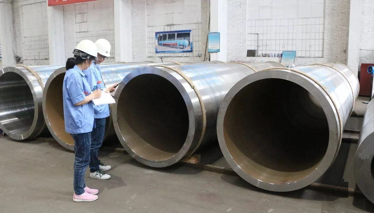
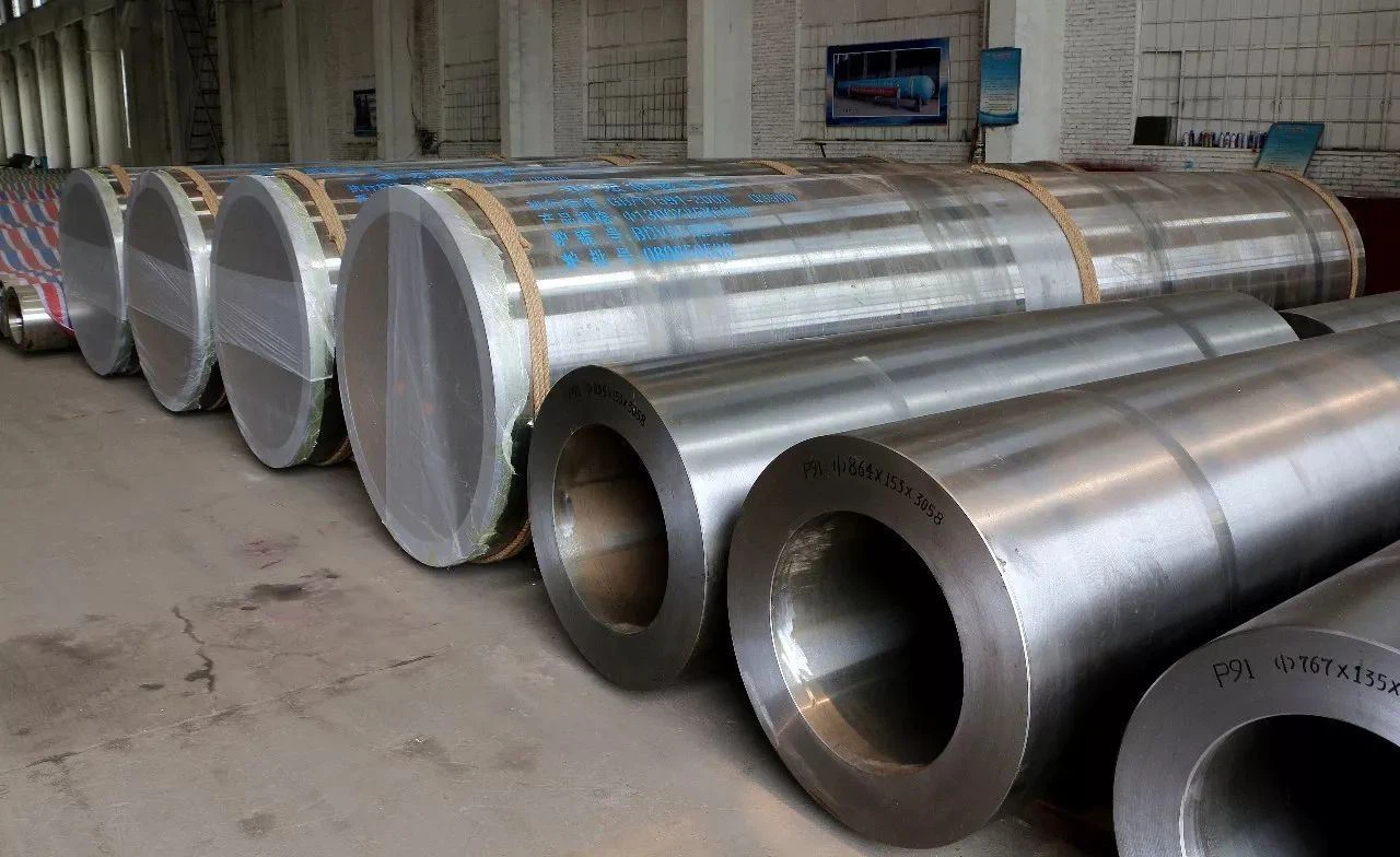
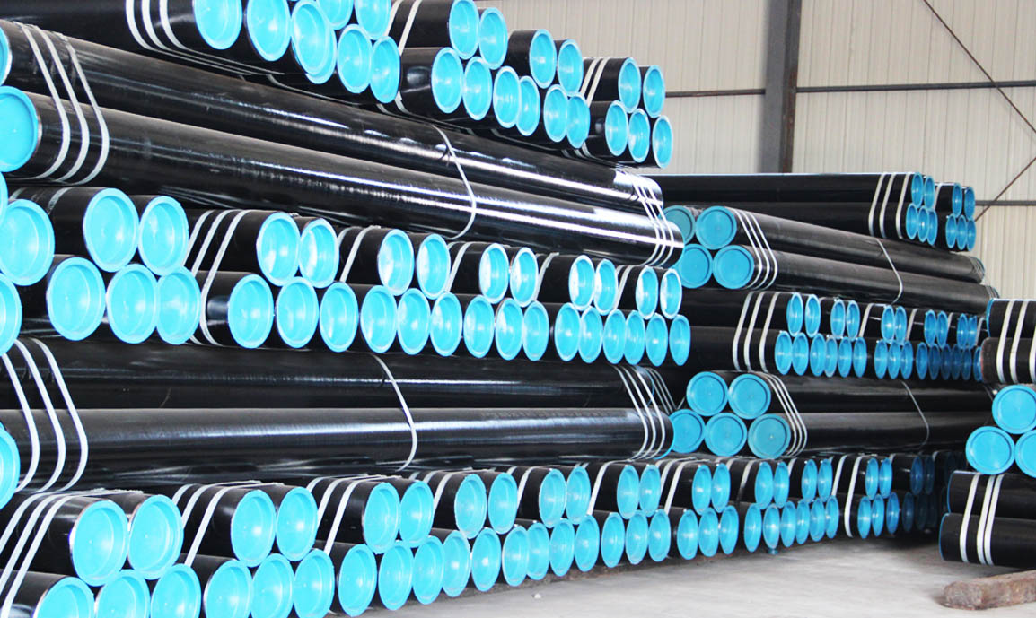
Large-diameter thick-walled seamless steel pipes are critical components in industries requiring robust materials capable of withstanding high pressures, extreme temperatures, and mechanical stresses. These pipes, characterized by outer diameters exceeding 200 mm and wall thicknesses often greater than 20 mm, are essential in applications such as high-pressure hydraulic cylinders, oil and gas pipelines, and heavy machinery. This document explores their production processes, material properties, mechanical behavior, and practical applications, with an emphasis on international material standards.
1. Production Processes
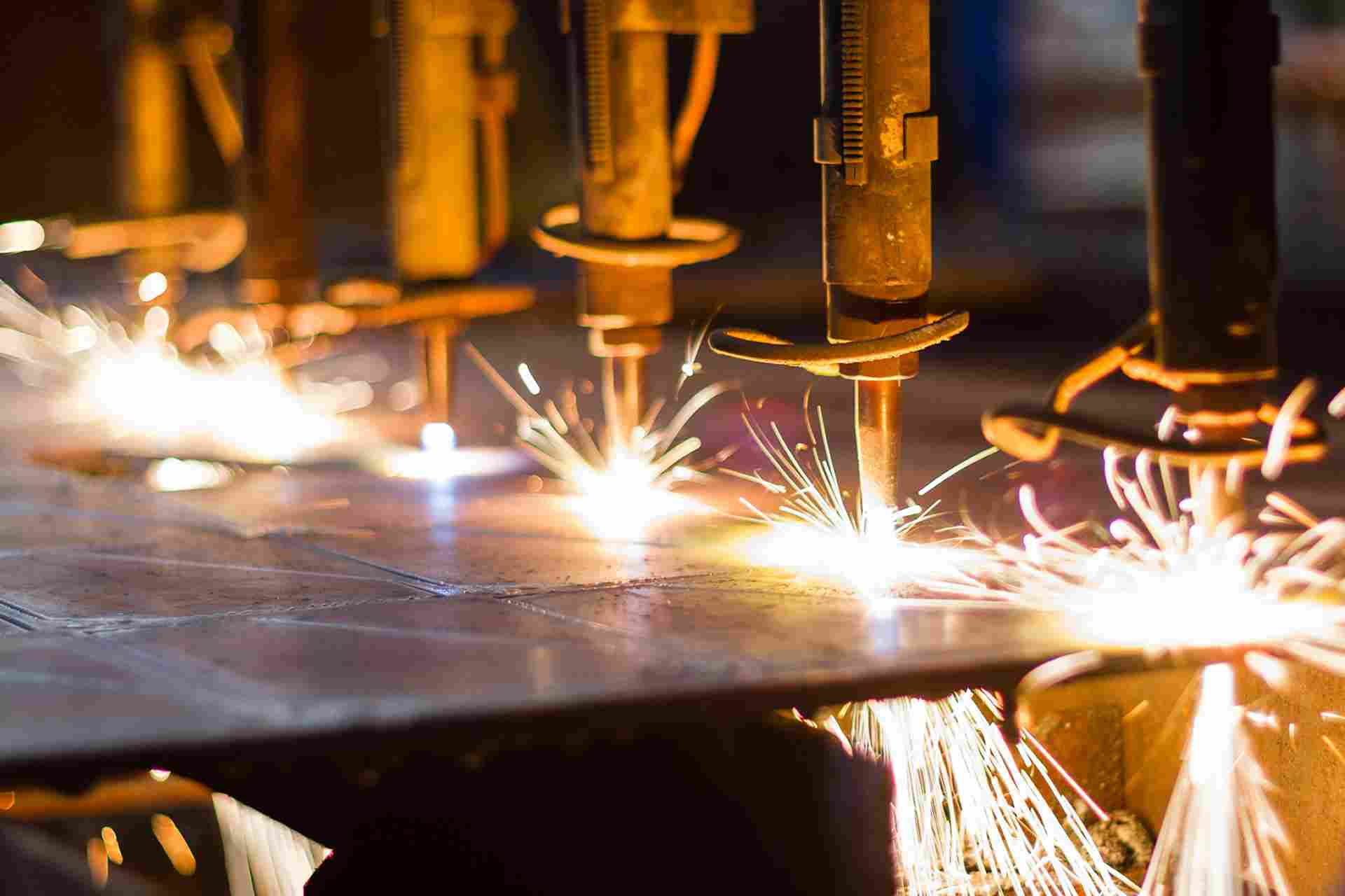
The manufacturing of large-diameter thick-walled seamless steel pipes involves sophisticated techniques to ensure structural integrity and dimensional precision. Below are the key stages:
1.1 Raw Material Selection and Billet Preparation
Production starts with high-quality steel billets, typically produced via electric arc furnace (EAF) or basic oxygen furnace (BOF) methods. Common materials include carbon steels (e.g., ASTM A106 Gr.B, 20#) and alloy steels (e.g., 42CrMo, 34CrMo4). Billets are inspected for chemical composition and internal defects using techniques like spectrometry and ultrasonic testing.
1.2 Hot Piercing
The billet is heated to 1100–1250°C in a rotary hearth furnace, then pierced using a Mannesmann piercing mill to create a hollow shell. This process ensures a seamless structure, with typical outer diameters ranging from 100 mm to 500 mm and wall thicknesses of 20–80 mm for large-diameter pipes.
1.3 Hot Rolling or Extrusion
The hollow shell is further processed via hot rolling (using a mandrel mill) or hot extrusion. Hot rolling suits diameters up to 600 mm, while extrusion is preferred for thick-walled sections (wall thickness/outer diameter ratio >0.1), offering superior uniformity and strength. Temperatures are maintained above 1000°C to enhance ductility.
1.4 Cold Finishing (Optional)
For applications requiring precise tolerances (e.g., ±0.1 mm) or smooth surfaces, cold drawing or cold rolling is applied. This increases yield strength through work hardening and refines the pipe’s dimensions, critical for hydraulic cylinder barrels.
1.5 Heat Treatment
Heat treatment enhances mechanical properties:
- Normalizing: Heating to 850–900°C and air cooling to relieve stresses.
- Quenching and Tempering: Quenching at 860°C and tempering at 500–600°C (e.g., for 42CrMo) to achieve high strength and toughness.
Inner surfaces may be honed to a finish of Ra ≤ 0.4 μm for hydraulic applications.
1.6 Quality Control
Finished pipes undergo rigorous testing, including hydrostatic pressure tests (up to 100 MPa), ultrasonic flaw detection, and dimensional checks, ensuring compliance with standards like ASTM A519, EN 10297-1, or GB/T 8162.
2. Material Specifications and Properties
Material choice depends on pressure, temperature, and environmental conditions. Two tables are provided below: one for common Chinese grades (GB standards) and another for European (EN) and American (ASTM/ASME) grades widely used in international markets.
2.1 Chinese Material Standards (GB)
| Grade | Standard | Yield Strength (MPa) | Tensile Strength (MPa) | Wall Thickness Range (mm) | Key Alloying Elements |
|---|---|---|---|---|---|
| 20# | GB/T 8162 | ≥410 | ≥550 | 10–50 | C: 0.17–0.24, Mn: 0.35–0.65 |
| 45# | GB/T 8162 | ≥600 | ≥750 | 10–50 | C: 0.42–0.50, Mn: 0.50–0.80 |
| 16Mn (Q345) | GB/T 1591 | ≥345 | ≥470 | 15–60 | C: ≤0.20, Mn: 1.00–1.60 |
| 42CrMo | GB/T 3077 | ≥650 | ≥850 | 20–80 | C: 0.38–0.45, Cr: 0.90–1.20, Mo: 0.15–0.25 |
2.2 European and American Material Standards (EN and ASTM/ASME)
| Grade | Standard | Yield Strength (MPa) | Tensile Strength (MPa) | Wall Thickness Range (mm) | Key Alloying Elements |
|---|---|---|---|---|---|
| P355N | EN 10216-3 | ≥355 | 490–630 | 10–60 | C: ≤0.20, Mn: 0.90–1.70 |
| 34CrMo4 | EN 10297-1 | ≥650 | ≥900 | 20–80 | C: 0.30–0.37, Cr: 0.90–1.20, Mo: 0.15–0.30 |
| A106 Gr.B | ASTM A106 | ≥240 | ≥415 | 10–50 | C: ≤0.30, Mn: 0.29–1.06 |
| A519 4140 | ASTM A519 | ≥655 | ≥855 | 20–80 | C: 0.38–0.43, Cr: 0.80–1.10, Mo: 0.15–0.25 |
| A335 P22 | ASTM A335 | ≥205 | ≥415 | 15–60 | C: ≤0.15, Cr: 1.90–2.60, Mo: 0.87–1.13 |
Notes: Yield and tensile strengths may vary based on heat treatment and wall thickness. European grades like P355N and 34CrMo4 are common in pressure vessels, while ASTM grades like A519 4140 excel in high-pressure hydraulic applications.
3. Mechanical Analysis
3.1 Hoop Stress
Hoop stress (σ_h) is the dominant stress in pressurized pipes:
σ_h = (P × D_i) / (2 × t)
Example: P = 80 MPa, D_i = 300 mm, t = 40 mm, σ_h = (80 × 300) / (2 × 40) = 300 MPa, safe for A519 4140 (σ_y = 655 MPa).
3.2 Wall Thickness Design
Minimum wall thickness (t_min) incorporates a safety factor (SF = 2):
t_min = (P × D_i) / (2 × σ_y / SF)
For P = 80 MPa, D_i = 300 mm, σ_y = 655 MPa, t_min = (80 × 300) / (2 × 655 / 2) = 36.64 mm, so t = 40 mm is adequate.
3.3 Burst Pressure
Burst pressure (P_burst) indicates failure threshold:
P_burst = (2 × σ_u × t) / D_i
For A519 4140 (σ_u = 855 MPa), P_burst = (2 × 855 × 40) / 300 = 228 MPa, a significant margin above 80 MPa.
3.4 Fatigue Considerations
For cyclic loading, the endurance limit (σ_e ≈ 0.4–0.5 × σ_u) must exceed stress amplitude. For 34CrMo4 (σ_u = 900 MPa), σ_e ≈ 400–450 MPa, ensuring durability.
4. Applications
4.1 High-Pressure Hydraulic Cylinders
Grades like A519 4140 and 34CrMo4 are used in heavy equipment (e.g., excavators, presses), handling 50–100 MPa and forces up to 1000 tons.
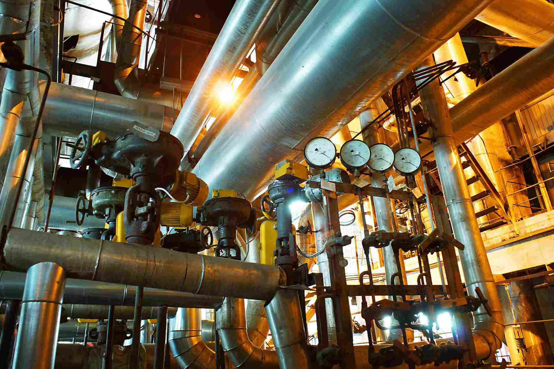
4.2 Oil and Gas Transportation
A106 Gr.B and P355N pipes with 30–60 mm walls transport high-pressure hydrocarbons, resisting corrosion and fatigue.
4.3 Heavy Machinery and Marine Systems
In cranes and offshore platforms, 42CrMo or A335 P22 pipes endure dynamic loads and harsh environments.
4.4 Power Generation
A335 P22 and similar grades in power plant boilers handle high-temperature steam up to 540°C and 10 MPa.
5. Practical Design Example
For a hydraulic cylinder with P = 90 MPa, outer diameter = 400 mm, using A519 4140:
- D_i = 340 mm, t = 30 mm
- σ_h = (90 × 340) / (2 × 30) = 510 MPa (<655 MPa)
- t_min = (90 × 340) / (2 × 655 / 2) = 46.72 mm (requires thicker wall)
- P_burst = (2 × 855 × 30) / 340 = 150.88 MPa
A 40 mm wall yields σ_h = 382.5 MPa, ensuring safety with SF adjustment.
ERW BLACK Pipes. Electric Resistance Welded (ERW) Pipes are manufactured from Hot Rolled Coils / Slits. All the incoming coils are verified based on the test certificate received from steel mill for their chemistry and mechanical properties. ERW pipe is cold-formed into a cylindrical shape, not hot-formed.
Seamless pipe is manufactured by extruding the metal to the desired length; therefore ERW pipe have a welded joint in its cross-section, while seamless pipe does not have any joint in its cross-section through-out its length. In Seamless pipe, there are no welding or joints and is manufactured from solid round billets.
Carbon steel seamless pipe is used in a range of applications in all different industries, including petrochemical, environmental, energy, and more. Thanks to more than 100 years of combined experience and vast knowledge across multiple industries, we can help match you with the right product for your unique application. Our friendly, knowledgeable customer service representatives will listen to your needs and can offer suggestions to get you products that meet your requirements.

The 3 elements of pipe dimension Dimension Standards of carbon and stainless steel pipe (ASME B36.10M & B36.19M) Pipe Size Schedule (Schedule 40 & 80 steel pipe means) Means of Nominal Pipe Size (NPS) and Nominal Diameter (DN) Steel Pipe Dimension Chart (Size chart) Pipe Weight Class Schedule (WGT)
Seamless pipes are manufactured using a piercing process, where a solid billet is heated and pierced to form a hollow tube. Welded pipes, on the other hand, are formed by joining two edges of steel plates or coils using various welding techniques.
Carbon steel pipe is highly resistant to shock and vibration which making it ideal to transport water, oil & gas and other fluids under roadways. Dimensions Size: 1/8″ to 48″ / DN6 to DN1200 Thickness: Sch 20, STD, 40, XS, 80, 120, 160, XXS Type: Seamless or welded pipe Surface: Primer, Anti rust oil, FBE, 2PE, 3LPE Coated Material: ASTM A106B, A53, API 5L B, X42, X46, X52, X56, X60, X65, X70 Service: Cutting, Beveling, Threading, Grooving, Coating, Galvanizing