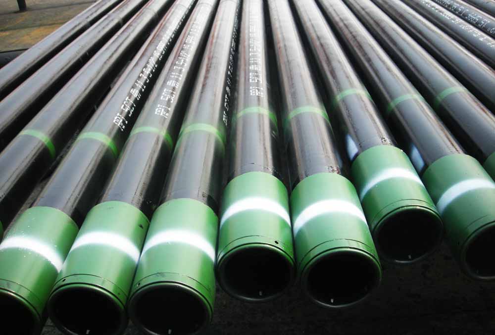
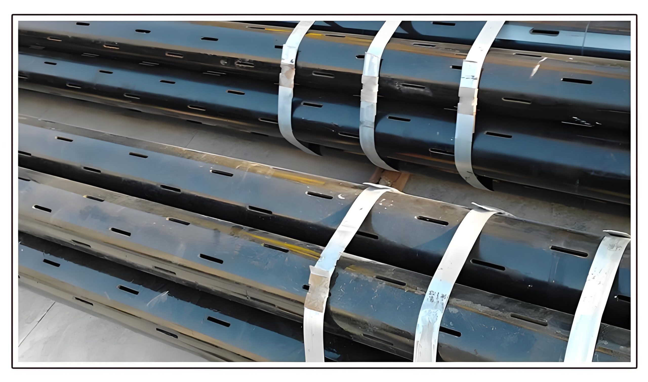
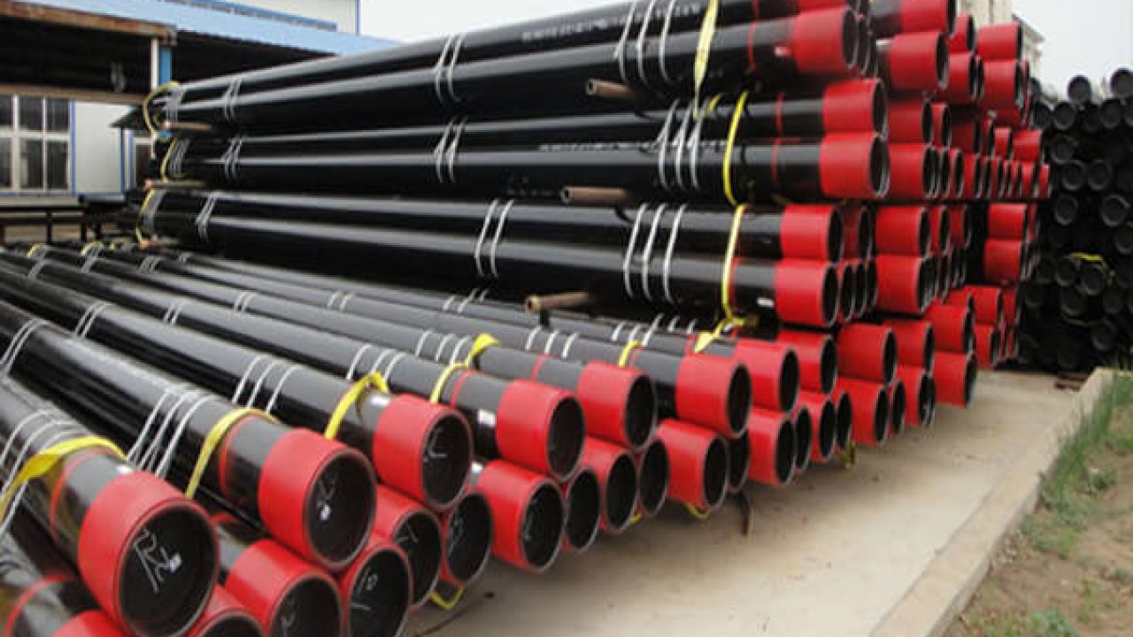
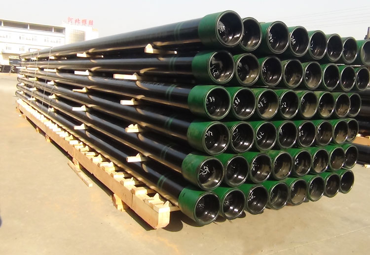
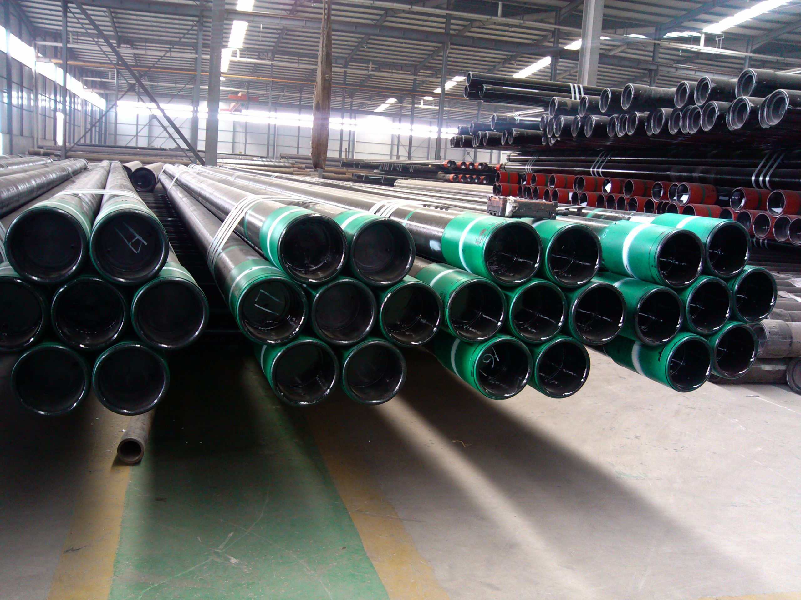
Slotted Casing Pipe

Slotted Casing Pipe for Oil Exploration
Casing Slotted Pipe
- Outside Diameter (O.D.):
- Casing: 4 1/2″ – 20″ (114.3mm – 508mm)
- Tubing: 1.05″ – 4 1/2″ (26.7mm – 114.3mm)
- Length:
- R1: 4.88 – 7.62M
- R2: 7.621 – 10.36M
- R3: 10.36 – 14.63M
- Wall Thickness (W.T.): 0.205” – 0.875” (5.21mm – 22.22mm)
- Product Standards: API 5CT, BS EN ISO11960, NFM87-207, JIS G3439, ISO 4270, GOST 632-80
- Material Grades: H40, J55, K55, N80-1, N80Q, R95, L80-1, L80-9Cr, L80-13Cr, C90, T95, C110, P110, Q125
Thread Types
- Casing: STC, LTC, BTC, etc.
- Tubing: NU, EU, XL, PH-4, PH-6, LTC, STC, BTC, etc.
Introduction
Slotted casing pipes are essential in oil exploration for sand control, enhancing well integrity, and increasing the stability of the well. Various slot types and patterns are used to optimize performance based on the specific conditions of the oil well.
| API Casing | ID mm |
Length m |
Slot Length mm |
Slot No.No./m
|
Slot width mm
|
Slot Tolerance
|
Valid Filter Area cm/m
|
Max. Strength KN
|
||
| Spec mm |
Thickness mm |
Per Weight kg/m |
||||||||
| 60.32 | 5 | 6.84 | 50.3 | 3
|
80
|
200 | 0.3
|
±50
|
48 | 512.54 |
| 73.02 | 5.5 | 9.15 | 62 | 240 | 57.6 | 688.55 | ||||
| 88.9 | 6.5 | 13.22 | 75.9 | 280 | 67.2 | 995.1 | ||||
| 101.6 | 6.5 | 15.22 | 88.6 | 300 | 72 | 1151.2 | ||||
| 114.3 | 7 | 18.47 | 100.3 | 10
|
320 | 76.8 | 1400.4 | |||
| 127 | 7.52 | 22.13 | 112 | 340 | 81.6 | 1673.8 | ||||
| 139.7
|
7.72 | 25.11 | 124.3 | 360 | 86.4 | 1900.2 | ||||
| 9.17 | 29.48 | 121.4 | 360 | 86.4 | 2232.4 | |||||
| 168.3 | 8.94 | 35.09 | 150.4 | 400 | 96 | 2672.95 | ||||
| 177.8
|
8.05 | 33.68 | 161.7 | 440 | 105.6 | 2559.2 | ||||
| 9.19 | 38.19 | 159.4 | 440 | 105.6 | 2940.7 | |||||
Specifications
API Spec 5CT – Specification 5CT/ISO 11960,GB/T 19830-2011 Specification for Casing and Tubing, Eighth Edition, Petroleum and natural gas industries-Steel pipes for use as casing or tubing for wells
Mechanical Properties:
| Group | Grade | Type | Total elongation
under load % |
Yield Strength M pa | Tensile strength
min Mpa |
Hardness | ||
| min | max | HRC | HBW | |||||
| 1 | 2 | 3 | 4 | 5 | 6 | 7 | 8 | 9 |
| 2 | J55 | – | 0.5 | 379 | 552 | 517 | – | – |
| K55 | – | 0.5 | 379 | 552 | 655 | – | – | |
| N80 | 1 | 0.5 | 552 | 758 | 689 | – | – | |
| N80 | Q | 0.5 | 552 | 758 | 689 | – | – | |
| 3 | L80 | 1 | 0.5 | 552 | 655 | 655 | 23 | 241 |
| L80 | 9Cr | 0.5 | 552 | 655 | 655 | 23 | 241 | |
| L80 | 13Cr | 0.5 | 552 | 655 | 655 | 23 | 241 | |
| C90 | 0.5 | 621 | 689 | 689 | 25.4 | 255 | ||
| C95 | – | 0.5 | 655 | 724 | 724 | – | – | |
| T95 | 0.5 | 655 | 724 | 724 | 25.4 | 255 | ||
| P110 | – | 0.6 | 758 | 862 | 862 | – | – | |
| 4 | Q125 | All | 0.65 | 862 | 931 | 931 | – | – |
Chemical Composition
| Standard | Grade | Composition(%) | ||||||||||
| C | Si | Mn | P | S | Cr | Ni | Cu | Mo | V | AIs | ||
| API SPEC 5CT | J55K55 | 0.34~0.39 | 0.20~ 0.35 |
1.25~1.50 | ≤0.020 | ≤0.015 | ≤0.15 | ≤0.20 | ≤0.20 | ≤0.020 | ||
| (37Mn5) | ||||||||||||
| N80 | 0.34~0.38 | 0.20~ 0.35 |
1.45~1.70 | ≤0.020 | ≤0.015 | ≤0.15 | 0.11 ~0.16 |
≤0.020 | ||||
| (36 Mn2V) | ||||||||||||
| L80(13Cr) | 0.15~0.22 | ≤1.00 | 0.25~1.00 | ≤0.020 | ≤0.010 | 12.0~ 14.0 |
≤0.20 | ≤0.20 | ≤0.020 | |||
| P110 | 0.26~0.35 | 0.17~ 0.37 |
0.40~0.70 | ≤0.020 | ≤0.010 | 0.80~ 1.10 |
≤0.20 | ≤0.20 | 0.15 ~0.25 |
≤0.08 | ≤0.020 | |
Slotted Types
Perforated

Rectangular Slotted

Trapezoid Slotted

Bridge Slotted

Wire Wrapped Screen

Mechanical Cutting

Compound Slotted Pipe

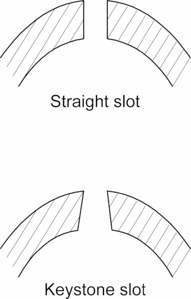
Slot Types
Straight Slots
Cut at a right angle to the liner, straight slots have uniform diameter from the inside to the outside of the wall. They are cost-effective but less efficient in sand control compared to keystone slots.
Keystone Slots
Cut at a slight angle, these slots are larger on the inside than on the outside, ensuring that particles entering the slot can pass through freely, reducing the risk of clogging.
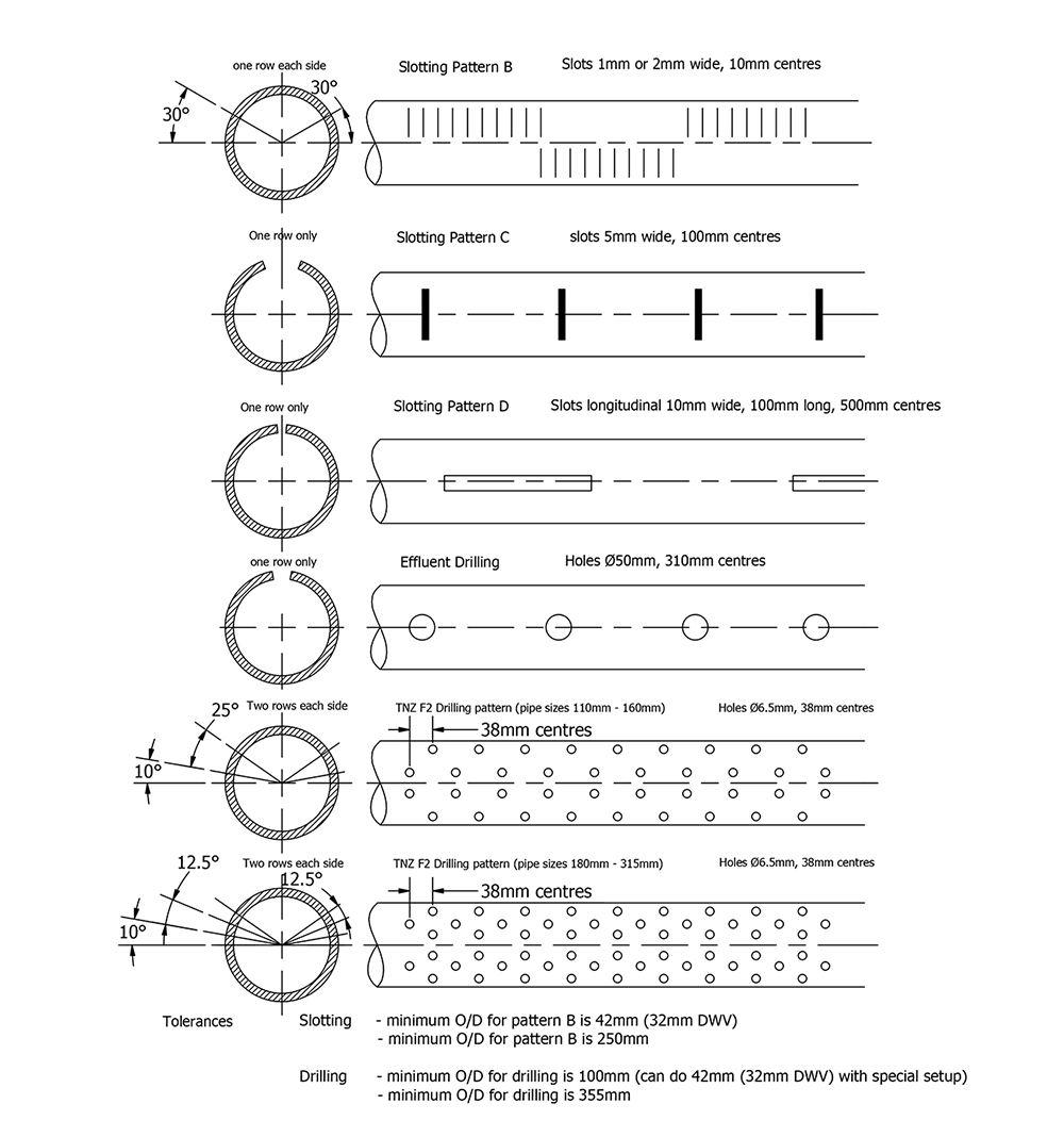
Slot Patterns
Line (Straight) Pattern
Slots are placed evenly in identical bands around the pipe, forming straight lines of slots across the length of the liner.
Single-Slot Staggered Pattern
Bands of evenly spaced slots are placed around the pipe, with slots in different bands offset (staggered) to each other. This pattern preserves the pipe’s strength and provides an even distribution of slots.
Gang Pattern (Multiple Staggered Pattern)
Similar to the single-slot staggered pattern but with two slots cut closely together at each position. This pattern withstands higher torque during installation and resists deformation under thermal load, making it suitable for Steam Assisted Gravity Drainage (SAGD) applications.
Quality Assurance
- Quality Systems: API/ISO
- Third-Party Inspections: SGS, DNV, BV, Moody
Conclusion
Slotted casing pipes are vital for preventing sand ingress, enhancing well strength, and maintaining the integrity and stability of oil wells. By selecting the appropriate slot type and pattern, operators can ensure efficient production and long-term well performance.
This comprehensive overview of slotted casing pipes provides detailed information on specifications, slot types, patterns, and quality assurance measures, ensuring a well-informed selection process for optimizing oil well performance.

