
UNS N08825 Nikel Tabanlı Alaşım Boru Hatları Kaynak İşlem Araştırması

Research on Welding Process of UNS N08825 Nickel-Based Alloy Pipelines
1. Introduction to UNS N08825 Nickel-Based Alloy
1.1 Chemical Composition and Material Properties
ABD N08825 (Incoloy 825) molibden ilaveli nikel-demir-krom alaşımıdır, bakır, ve titanyum. Its chemical composition is meticulously designed to achieve exceptional corrosion resistance and mechanical stability in harsh environments (#user-content-ref-1)(#user-content-ref-3):
- Nikel (38–46%): Enhances resistance to chloride-induced stress corrosion cracking and acidic media (örneğin, sulfuric and phosphoric acids).
- Krom (19.5–23.5%): Forms a protective oxide layer against oxidation and pitting corrosion.
- Molibden (2.5–3.5%) and Copper (1.5–3%): Improve resistance to reducing acids, particularly sulfuric acid.
- Titanyum (0.6–1.2%): Stabilizes the alloy against intergranular corrosion during welding.
Mechanical properties under ASTM/ASME standards include:
- Çekme mukavemeti: 550–585 MPa
- Verim gücü: 240–275 MPa
- Uzama: ≥% 30 (#user-content-ref-2)(#user-content-ref-6).
1.2 Applications in Industrial Sectors
This alloy is widely used in:
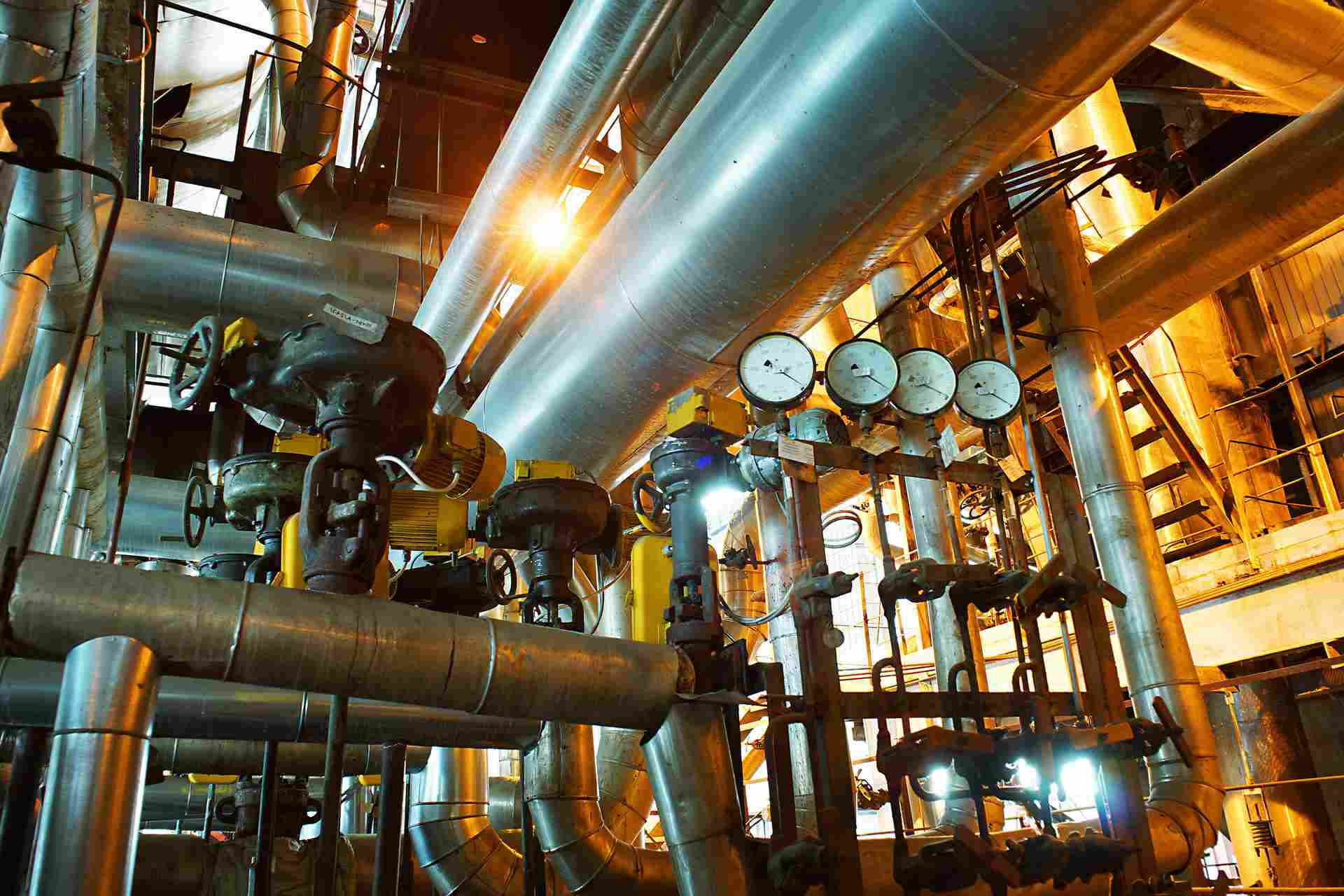
- Yağ & Gas: Denizaltı boru hatları, acid gas handling systems.
- Kimyasal İşleme: Reaktörler, ısı değiştiriciler.
- Nükleer güç: Coolant systems, spent fuel storage (#user-content-ref-5)(#user-content-ref-46).
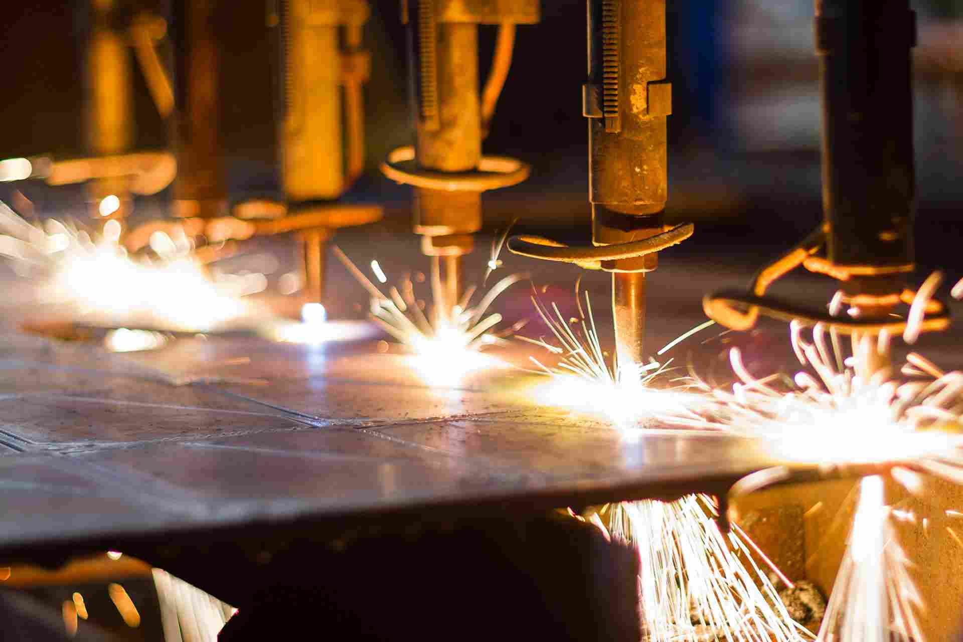
2. Welding Methods for UNS N08825 Pipelines
2.1 Common Welding Techniques
2.1.1 TIG (GTAW) Kaynak
- Avantajları: Precise heat control, yüksek kaliteli kaynaklar, minimal spatter.
- Parametreler:
- Current: 90–150 A (DCEN polarity).
- Voltage: 10–15 V.
- Shielding gas: Argon or Ar-He mixtures (flow rate: 10–15 L/min) (#user-content-ref-7)(#user-content-ref-22).
- Uygulamalar: Root passes in critical pipelines requiring defect-free joints.
2.1.2 MİG (GMAW) Kaynak
- Avantajları: High deposition rates, suitable for thick-walled pipes.
- Parametreler:
- Current: 120–200 A.
- Wire feed speed: 4–8 m/min.
- Shielding gas: 98% Ar + 2% CO₂ (#user-content-ref-12)(#user-content-ref-24).
2.1.3 SMAW (Korumalı Metal Ark Kaynağı)
- Avantajları: Flexibility in field welding.
- Electrodes: AWS ENiCrMo-3 for matching corrosion resistance.
- Zorluklar: Requires skilled operators to manage slag inclusion risks (#user-content-ref-8)(#user-content-ref-11).
2.2 Welding Material Selection
- Dolgu Metalleri: Ernichrmo-3 (TIG/MIG) or ENiCrMo-3 (SMAW) to match base metal composition.
- Kaynak Öncesi Temizleme: Acetone or alcohol degreasing to remove sulfur, zinc, ve diğer kirleticiler (#user-content-ref-19)(#user-content-ref-35).
3. Optimization of Welding Parameters
3.1 Critical Parameters and Their Effects
| Parametre | Optimal Range | Impact on Weld Quality |
|---|---|---|
| Isı Girişi | 1.5–2.5 kJ/mm | Excessive input causes HAZ embrittlement (#user-content-ref-13). |
| Interpass Sıcaklığı | ≤150 ° C | Prevents carbide precipitation (#user-content-ref-20). |
| Travel Speed | 50–90 mm/min | High speed reduces dilution but risks lack of fusion (#user-content-ref-21). |
3.2 Örnek Olay İncelemesi: TIG Welding Parameter Optimization
A study on API 5L X-65 cladded UNS N08825 demonstrated:
- Optimal Parameters: 110 A, 12 V, 70 mm/min.
- Results:
- Tensile strength retention: 99.2% of base metal.
- Impact toughness in HAZ: 88–258 J (#user-content-ref-16).
4. Welding Defect Prevention and Control
4.1 Common Defects and Mitigation Strategies
| Defect Type | Causes | Preventive Measures |
|---|---|---|
| Sıcak Çatlama | Low-melting eutectics, stress | Use low-sulfur filler metals; preheat (100–150°C) (#user-content-ref-31). |
| Gözeneklilik | Moisture, contaminated shielding | Ensure gas purity (>99.995%); avoid drafts (#user-content-ref-35). |
| Lack of Fusion | Insufficient heat input | Increase current; reduce travel speed (#user-content-ref-36). |
4.2 Quality Assurance Standards
- ASTM B705: Specifies dimensional tolerances and mechanical testing for welded pipes.
- ISO 5817: Defects classification (Level B for critical applications) (#user-content-ref-28)(#user-content-ref-30).
5. Kaynak Sonrası Isıl İşlem (PWHT)
5.1 Requirements and Procedures
- Typical PWHT: 600–650°C for 1–2 hours to relieve residual stresses.
- Exceptions: Austenitic structure of UNS N08825 generally avoids PWHT unless specified for high-temperature service (>538°C) (#user-content-ref-38)(#user-content-ref-42).
5.2 Microstructural Considerations
- Carbide Precipitation: Minimized by rapid cooling (water quenching) post-PWHT.
- Stabilization Treatment: 885°C for 1.5 hours to enhance intergranular corrosion resistance (#user-content-ref-39).
6. Industry Applications and Case Studies
6.1 Yağ & Gaz Sektörü
- Subsea Pipeline Welding: TIG root + MIG fill/cap processes achieve X-ray compliance (100% pass rate) (#user-content-ref-12).
- Örnek Olay İncelemesi: A 2024 project by Sinopec utilized UNS N08825 for sour gas pipelines, reducing corrosion-related failures by 40% (#user-content-ref-43).
6.2 Nuclear Power Applications
- Coolant System Welds: Emn (Elektron ışını kaynağı) achieved 600 MPa tensile strength, matching base metal performance (#user-content-ref-17).
6.3 Kimyasal İşleme
- Acid Reactor Fabrication: SMAW with ENiCrMo-3 electrodes demonstrated 15-year service life in sulfuric acid environments (#user-content-ref-46).
7. Geleceğin Trendleri ve Yenilikleri
- Lazer hibrit kaynak: Combines laser and MIG for higher speed and deeper penetration.
- Katkı maddesi üretimi: Wire-arc AM (WAAM) for complex pipe geometries with UNS N08825 (#user-content-ref-17)(#user-content-ref-24).
Chemical composition and mechanical properties of UNS N08825 nickel-based alloy
UNS N08825 nickel-based alloy (commonly known as Incoloy 825) is an austenitic iron-chromium-nickel alloy, the main components of which include nickel, krom, molibden, copper and a small amount of iron, titanyum, aluminum and other elements. Its chemical composition and mechanical properties are as follows:
Kimyasal bileşim
- Nikel (İçinde) : 38%-46%.
- Krom (CR) : 19.5%-23.5%.
- Molibden (Ay) : 2.5%-3.5%.
- Bakır (Cu) : 1.5%-3.5%.
- Ütü (Fe) : 22%-25%.
- Silikon (Ve) : 0.5%.
- Manganez (Mn) : 1.0%.
- Sülfür (S) : 0.03%.
- Fosfor (P) : 0.03%.
Mekanik özellikler
- Verim gücü : 725 MPa.
- Çekme mukavemeti : 550 MPa.
- Uzama : ≥% 30.
- Brinell hardness : ≤135-165.
- Esneklik modülü : 28.3 x 10⁶ kN/mm² (196 KN/mm²).
Özellikler
- Korozyon direnci : Excellent corrosion resistance, especially in reducing and oxidizing environments, and performs well against media such as sulfuric acid, fosforik asit, chlorides and hydroxides.
- Yüksek sıcaklık performansı : It still maintains good mechanical properties in high temperature environments above 700°C.
- Oxidation resistance : In a high-temperature oxidation environment, the surface oxide layer is thinner, which delays the wear and aging of the material.
- Kaynak performansı : easy to form and weld, and not easily sensitized during the welding process.
Özetle, UNS N08825 nickel-based alloy has been widely used in chemical industry, deniz mühendisliği, nuclear industry and high-temperature heat exchangers due to its excellent corrosion resistance and high-temperature performance.
UNS N08825 Common welding process methods (TIG/MIG/SMAW, vesaire.)
ABD N08825 (Incoloy 825) is a nickel-based alloy with excellent corrosion resistance and high temperature performance. It is widely used in petrochemical, Deniz Mühendisliği ve diğer alanlar. Its common welding methods include TIG (tungsten inert gas welding), MİG (metal inert gaz kaynağı) and SMAW (manual arc welding).
- TIG (Tungsten Inert Gas Welding)
TIG welding is suitable for thin plates and situations where high-quality welded joints are required. This method uses a non-consumable tungsten electrode and inert gas (such as argon) to protect the welding area, which can accurately control the heat input and reduce the structural changes in the heat-affected zone of the weld, thereby improving the welding quality. - MİG (Metal Inert Gas Welding) :
MIG welding is suitable for welding medium and thick plates. It can achieve high production efficiency and good welding performance by continuously consuming welding wire and protecting the welding area with inert gas. This method is suitable for thick plate welding, but it requires strict control of welding heat input to avoid structural changes. - SMAW (Manual Metal Arc Welding) :
SMAW is a traditional welding method that is suitable for materials of various thicknesses. This method melts the metal through an arc between the electrode and the workpiece, and the electrode protects the weld area during the melting process. Although the production efficiency is low, it is simple to operate and is suitable for welding small-diameter pipes and base welds.
Ek olarak, the following points should be noted during the welding process of UNS N08825 alloy:
- Welding material selection : AWS ERNiCrMo-3 welding wire or electrode is recommended to ensure the corrosion resistance and mechanical properties of the welded joint.
- Welding parameter control : Reasonable selection of welding current, voltage and gas flow to optimize welding quality and reduce defects.
- Post-treatment : For thick plate welding, heat treatment may be required to eliminate stress concentrations and improve the microstructure.
Özetle, there are various welding process methods for UNS N08825 alloy. TIG, MIG and SMAW are all commonly used methods. The specific selection needs to be considered comprehensively based on the workpiece thickness, welding position and quality requirements.
① Characteristics of heat affected zone of medium material welding
According to the existing data, the research on the characteristics of the heat affected zone (HAZ) of UNS N08825 nickel-based alloy welding mainly focuses on the following aspects:
- Welding performance and microstructure :
- UNS N08825 alloy has excellent corrosion resistance and high temperature performance, but its welding process is relatively complicated, and the microstructure changes and welding quality of the welded joint directly affect its performance.
- Kaynak sırasında, high nickel content and the distribution of alloying elements have a significant impact on the welding performance and may lead to a decrease in the mechanical properties of the welded joint.
- Microstructure and properties of heat affected zone :
- Studies have shown that the microstructure of the heat-affected zone of welding will change significantly, the grain shape and size will become coarser, resulting in a decrease in the mechanical properties of the material.
- In the Charpy impact test, the minimum impact value of the HAZ area is significantly lower than that of the base material area, indicating that the toughness of the HAZ is poor.
- Influence of welding process on HAZ :
- Different welding methods (such as laser welding, elektron ışını kaynağı, vesaire.) have different effects on the microstructure and properties of HAZ. Laser welding can improve the mechanical properties and microstructure of the joint.
- Process parameters such as welding heat input, restraint, pre-weld heat treatment and post-weld heat treatment have an important influence on the crack sensitivity and mechanical properties of HAZ.
- Effect of heat treatment on HAZ :
- Reasonable heat treatment process can optimize the structure and properties of HAZ and reduce the sensitivity of liquefaction cracks.
- Appropriate heat treatment at high temperature (such as solution treatment and stabilization treatment) can improve the corrosion resistance and mechanical properties of HAZ.
- Challenges in practical applications :
- Pratik uygulamalarda, the corrosion resistance and mechanical properties of welded joints need to be guaranteed by strict welding process and heat treatment.
- Welded joints in high temperature environments may face the risk of intergranular corrosion and stress corrosion cracking, and special attention should be paid to post-welding heat treatment and anti-corrosion measures.
Özetle, the research focus of the heat affected zone of UNS N08825 nickel-based alloy welding is to optimize the welding process and heat treatment parameters to improve the mechanical properties and corrosion resistance of HAZ and ensure the reliability of welded joints in high temperature and corrosive environments.
②Process parameter optimization plan (current/voltage/speed, vesaire.)
To optimize the TIG, MIG and SMAW process parameters (including current, voltage and speed) of UNS N08825 alloy welding to improve welding quality and efficiency, you can refer to the following suggestions:
1. TIG kaynağı
- Current : The current directly affects the weld depth and width. For N08825 alloy, it is recommended to control the current between 90 Ve 110 A to avoid undercutting and burn-through caused by too small a current, and to avoid excessive weld width caused by too large a current.
- Voltage : The voltage should be controlled between 11 Ve 13 V to ensure good arc stability and weld formation quality.
- Speed : The welding speed should be controlled between 50 Ve 90 mm/min to obtain good weld formation and lower heat input, thereby reducing welding defects.
- Shielding gas : Use argon or helium as shielding gas to ensure stability and weld quality during welding.
2. MIG kaynağı
- Current : Current has a significant effect on weld penetration and width. The recommended current range is 140~150 A to ensure good weld formation and mechanical properties.
- Voltage : Voltage has an important influence on weld quality and mechanical properties. It is recommended to control the voltage between 20 Ve 25 V to optimize the tensile strength and hardness of the weld.
- Speed : The welding speed should be adjusted according to the material thickness and welding position. Genel olarak, the recommended speed is 20~30 cm/min to ensure the uniformity and mechanical properties of the weld.
- Gas flow rate : The protective gas flow rate should be controlled at 15~20 L/min to prevent oxidation and contamination.
3. SMAW welding
- Current : The current directly affects the degree of melting of the weld. It is recommended that the current be controlled between 100 Ve 150 A to ensure uniform melting and forming of the weld.
- Voltage : The voltage should be adjusted according to the thickness of the welding material and the welding position. It is generally recommended to control the voltage between 20~25 V to optimize the weld quality and mechanical properties.
- Speed : The welding speed should be controlled at 5~10 cm/min to ensure uniform melting and forming of the weld.
4. Comprehensive Optimization Method
- Taguchi method : Optimizing welding parameters by Taguchi method can effectively improve welding quality and efficiency. Örneğin, the L9 orthogonal experimental array is used to analyze the effects of welding current, voltage and speed on weld performance and determine the optimal parameter combination.
- Grey correlation analysis : Grey correlation analysis is used to evaluate the influence of different parameters on weld performance and further optimize welding parameters.
- Genetic Algorithm : Genetic algorithm is used for multi-objective optimization to balance welding quality and production efficiency.
5. İşleme sonrası
- Annealing treatment : Proper annealing treatment should be carried out after welding to eliminate welding internal stress and improve the ductility and plasticity of the weld.
- Solution treatment : Solution treatment is used to optimize the microstructure of the weld and improve its mechanical properties.
6. Notalar
- Temizlik : Ensure the welding environment is pollution-free and remove oxides and contaminants on the surface of the material.
- Shielding gas : Choose appropriate shielding gas, such as argon or helium, to ensure stability and weld quality during welding.
- Heat input control : Strictly control welding heat input to avoid overheating leading to intergranular corrosion and other welding defects.
Through the above methods, the TIG, MIG and SMAW welding process parameters of UNS N08825 alloy can be effectively optimized to improve the welding quality and efficiency.
UNS N08825 Welded Joint Quality Control Standard
The quality control standards for UNS N08825 welded joints are mainly based on the following specifications and standards:
- ASTM B705-05 : This standard is specifically for the specification of welded pipes made of nickel alloys (including UNS N08825), covering the design of welded joints, malzeme seçimi, welding procedures, and quality control requirements.
- ASME BPVC.II.B-2019 : This specification is consistent with ASTM B704-07 and is applicable to the manufacture of UNS N08825 alloy welded pipes, emphasizing the corrosion resistance and mechanical property requirements of welded joints.
- ISO 5817:2015 : This international standard provides general guidance for the quality control of welded joints. It applies to fusion welded joints in nickel-base alloys, including methods for the assessment of defects and the selection of quality grades.
- ASTM B163 and ASTM B423 : These standards specify the chemical composition, mechanical properties and heat treatment process requirements for seamless and welded pipes, sırasıyla, and provide technical support for the production implementation of UNS N08825.
- Welding process optimization : To ensure the quality of the welded joint, it is necessary to strictly control the heat input (1.5-2.5 kJ/mm), select suitable welding materials (such as ERNiCrMo-3), and use TIG or MIG technology to reduce the risk of embrittlement in the heat-affected zone.
- Post-heat treatment : Uygun ısı sonrası tedavi (usually between 600-650°C) is required after welding to optimize the microstructure and improve corrosion resistance.
- Inspection and evaluation : Performance testing of welded joints includes mechanical properties testing, microstructure analysis and corrosion resistance testing to ensure that they meet application requirements.
Özetle, the quality control standards for UNS N08825 welded joints are mainly based on specifications such as ASTM B705-05, ASME BPVC.II.B-2019 and ISO 5817:2015, combined with specific welding process optimization and post-heat treatment requirements to ensure the corrosion resistance, mechanical properties and long-term stability of the welded joints.
②Preventive measures for welding defects (cracks/pores/lack of fusion, vesaire.)
To prevent defects such as cracks, pores and lack of fusion during the welding process of UNS N08825, the following measures can be taken:
- Prevention of cracks :
- Control welding stress : Reduce welding stress by preheating and controlling the cooling rate, thereby reducing the risk of cracks.
- Choose appropriate welding materials : Use welding rods or welding wires with a composition similar to that of the parent material to ensure the microstructure and mechanical properties of the welded joint.
- Optimize welding parameters : adjust welding current, voltage and speed to avoid too fast cooling rate and excessive heat input.
- Post-weld treatment : Perform appropriate post-weld heat treatment to eliminate residual stress and improve the performance of the welded joint.
- Prevention of stoma :
- Clean the weldment surface : Make sure there is no oil, pas, water or other impurities on the weldment and welding wire surface, especially within 20-30mm on both sides of the groove.
- Choose the right shielding gas : Use high-purity (örneğin 99.996%) argon as the shielding gas to ensure the gas shielding effect during the welding process.
- Control welding speed and current : reduce welding speed and current appropriately to avoid incomplete gas escape caused by too fast welding speed.
- Proper drying of welding rods and flux : Make sure welding rods and flux are fully dried before use to avoid hydrogen porosity caused by moisture.
- Prevention of unfusion :
- Control welding parameters : ensure that the welding current and voltage are sufficient to avoid incomplete fusion due to low current.
- Clean the groove surface : Thoroughly clean the impurities on the groove surface before welding to ensure the cleanliness of the weld edge.
- Adjust welding angle and speed : Properly adjust welding angle and speed to avoid incomplete fusion due to improper angle or excessive speed.
- Comprehensive measures :
- Choose the appropriate welding process : Choose the appropriate welding process according to the specific working conditions, such as short arc operation, stable arc and arc stop, vesaire.
- Strengthen welding inspection : Carry out strict inspection during the welding process to detect and correct defects in time.
- Optimize the welding environment : Keep the welding environment clean and dry to avoid the influence of moisture and impurities in the air on the welding quality.
Yukarıdaki önlemlerle, defects such as cracks, pores and lack of fusion during the welding process of UNS N08825 can be effectively prevented to ensure welding quality and corrosion resistance.
UNS N08825 Post-weld heat treatment process requirements
The post-weld heat treatment process requirements for UNS N08825 nickel-based alloy are as follows:
- Necessity of heat treatment :
According to the UNS N08825 nickel-based alloy, post-weld heat treatment is generally not required, but in certain circumstances (such as design documents or technical conditions require), heat treatment is required to eliminate residual stress or improve the performance of the welded joint. - Heat treatment temperature :
If heat treatment is required, the common temperature range is 600-650°C, and the specific temperature needs to be determined according to the design documents or relevant technical conditions. - Heat treatment method :
Heat treatment usually adopts the method of heating in the furnace, including the control of heating rate, holding time and cooling method, vesaire. For long weldments, they can be heated in sections and insulation measures can be taken. - Heat treatment purpose :
The main purpose of heat treatment is to eliminate welding residual stress and improve the structure and properties of the welded joint, thereby improving corrosion resistance and mechanical properties. - Not :
- The welding heat input should be strictly controlled within the range of 1.5-2.5 kJ/mm² to avoid overheating leading to intergranular corrosion or brittle phase precipitation.
- During the heat treatment process, it is necessary to prevent the precipitation of grain boundary carbides, especially the residence time in the sensitization zone (450-800°C) should not be too long.
- The hardness value of the weld after heat treatment shall comply with the requirements of the welding procedure specification.
- Special Requirements :
- For environments prone to stress corrosion (such as wet H2S corrosive environment), post weld heat treatment is necessary.
- Standard corrosion testing should be performed after heat treatment to monitor material properties.
Özetle, the post-weld heat treatment process of UNS N08825 nickel-based alloy needs to be formulated according to specific design documents and technical conditions, usually carried out in the range of 600-650°C, with the focus on eliminating residual stress and improving the performance of welded joints.
Related industry application cases (petroleum/chemical/nuclear power, vesaire.)
Here are some application cases in the petroleum, chemical and nuclear power industries:
- Petrol Endüstrisi :
- Shengli Petroleum Engineering Company’s “Application of Internet of Things in Petroleum Engineering Equipment Management” project was selected as a typical case of Internet of Things empowering industry development in 2024 by the Ministry of Industry and Information Technology, demonstrating the application of Internet of Things technology in petroleum engineering equipment management.
- Guangzhou Petrochemical has improved the safety and environmental protection indicators of the petrochemical industry through 5G+ information technology, becoming a demonstration case in Guangdong Province and even the whole country.
- Yokogawa provides comprehensive solutions in the oil and gas industry, from the LNG supply chain to downstream oil and gas, covering natural gas liquefaction, toplu taşıma, and regasification.
- Chemical Industry :
- The application of polypropylene pipe (PP pipe) in chemical wastewater treatment, kimyasal reaktörler, corrosive liquid transportation and pump station pipelines demonstrates its advantages such as corrosion resistance and high temperature resistance.
- The application of PPH+FRP composite materials in the chemical industry, including PPH+FRP towers, storage tanks and liquid collectors, has improved the performance and safety of chemical equipment.
- Companies such as Xinhua Guangdong Petrochemical and Xinghuo Silicone have applied 5G technology to scenarios such as production unit simulation, equipment predictive maintenance, and global logistics monitoring, promoting the digital transformation of the chemical industry.
- Nuclear power industry :
- China’s nuclear power industrial Internet platform was selected as one of the “Fifth Global Industrial Internet Conference Integration and Innovation Application Cases”, demonstrating the practice of nuclear power digital transformation based on the industrial Internet platform.
- The “Guohe No. 1” demonstration project successfully applied 5G technology, providing the nuclear power industry with smart and information-based modern construction site experience.
- The application of AI technology in nuclear power engineering and test production, including intelligent production and quality control, supply chain management and risk prevention, has significantly improved business efficiency and safety.
ERW SİYAH Borular. Elektrik Direnci Kaynaklı (DÖNÜM) Borular Sıcak Haddelenmiş Rulolardan Üretilmektedir / Yarıklar. Gelen tüm bobinler, kimya ve mekanik özellikleri açısından çelik fabrikasından alınan test sertifikasına göre doğrulanır.. ERW boru soğuk şekillendirilerek silindirik bir şekle dönüştürülür, sıcak şekillendirilmemiş.
Dikişsiz boru, metalin istenilen uzunlukta ekstrüde edilmesiyle üretilir.; bu nedenle ERW borusunun kesitinde kaynaklı bir bağlantı bulunur, dikişsiz borunun kesitinde uzunluğu boyunca herhangi bir bağlantı bulunmazken. Dikişsiz boruda, kaynak veya ek yeri yoktur ve sağlam yuvarlak kütüklerden üretilmiştir.

The 3 boru boyutu elemanları Karbon ve paslanmaz çelik borunun Boyut Standartları (ASME B36.10M & B36.19M) Boru Boyutu Tablosu (Takvim 40 & 80 çelik boru anlamına gelir) Nominal Boru Boyutu Ortalamaları (NPS'ler) ve Nominal Çap (DN) Çelik Boru Ölçü Tablosu (Boyut tablosu) Boru Ağırlık Sınıfı Programı (WGT)
Dikişsiz borular delme işlemi kullanılarak üretilir, içi boş bir tüp oluşturmak için katı bir kütüğün ısıtıldığı ve delindiği yer. Kaynaklı borular, diğer taraftan, Çelik levha veya bobinlerin iki kenarının çeşitli kaynak teknikleri kullanılarak birleştirilmesiyle oluşturulur..
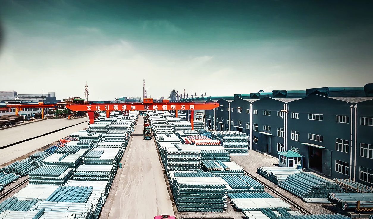
Karbon çelik boru şok ve titreşime karşı oldukça dayanıklıdır, bu da onu suyun taşınması için ideal kılar, yağ & Karayollarının altındaki gaz ve diğer sıvılar. Boyutlar Boyut: 1/8″ ila 48″ / DN6 ila DN1200 Kalınlık: Sch 20, CYBH, 40, XS, 80, 120, 160, XXS Türü: Dikişsiz veya kaynaklı boru Yüzeyi: Astar, Pas önleyici yağ, FBE, 2PE, 3LPE Kaplı Malzeme: ASTM A106B, A53, API 5LB, X42, X46, X52, X56, X60, X65, X70 Hizmeti: Kesme, Eğim verme, Diş açma, Kanal açma, Kaplama, Galvanizleme
Tip A- Yeterli kafa alanının mevcut olduğu yerlerde kullanılır. Belirli bir yükseklik arzu edilir. Tip B- Boşluk payının sınırlı olduğu yerlerde kullanılır. Kafa eki tek bir pabuçtur. Tip C- Boşluk payının sınırlı olduğu yerlerde kullanılır. Kafa eki yan yana çıkıntılardır